EUROMAP67 Interface
General information
Note
This document is intended solely as support for the installation/set-up/assembly of the application/component kit. This document is not an installation manual in the strict sense.
Safety notice
Seek professional assistance if necessary to avoid dangerous situations and injuries.
Make sure that you install a light curtain (safety device) between the robot and the injection molding machine so that the machine cannot close the mold when the robot is inside it. Failure to do so may result in serious material damage.
Before using the EUROMAP 67 interface, you should have read and understood the manual for the injection molding machine (SGM) and this user information in full. Stopping the SGM in the event of a safety stop of the robot is not provided for in the EUROMAP 67 standard. This means that the operator should not be able to reach the effective range of the SGM when entering the effective range of the robot, unless additional external protective equipment causes the SGM to stop when the operator enters or reaches into its area of action. If both the robot and the SGM are to be brought to a protective stop by a safety device, connect the device to the SGM.
Power supply
Switch off the robot system before starting the following steps. Once this has been completed, the electrical power supply can be switched on again.
The following link provides a complete description of the EUROMAP67 interface:
https://www.euromap.org/media/recommendations/67/2015/EU%2067_Ver_1.11_May2015.pdf
Tools required
- Allen key 2.5 mm
- Allen key 4 mm
Procedure
Connecting the EUROMAP interface
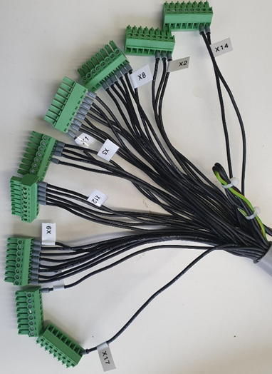
On the HORST side, the Phoenix terminal strips (green) must be plugged into the Control switch cabinet. |
| ||
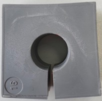
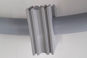
The cable gland (size 16) can be used to lead the connection cable out of Control with strain relief. To do this, the appropriate elements in the rubber cover on the control cabinet must be removed and replaced with the grey grommet. |
| ||
On the injection moulding machine side, the Harting plug is already pre-assembled ready for connection so that it can be connected to the opposite side of the machine |
| ||
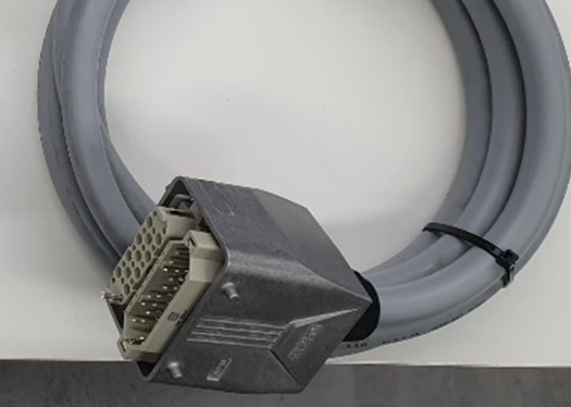
Signal description for HORST - injection moulding machine communication
For signal transmission, the exact pin assignment on the HORST side and the injection molding machine (SGM) side is described in the following tables.
On the HORST side, the injection molding signals can be controlled directly via the digital inputs and outputs. Some of the safety signals must still be configured in the horstOS software so that they receive the respective safety function. These signals are marked with a note in the table. The configuration in horstOS is described below.
Input signals HORST
Input signals HORST | Hints for the robot | Contact No. EUROMAP | Signal description EUROMAP |
TA (Internal OSSD) SI4A | horstOS Configuration of safety input as external emergency stop | ZA1 | Emergency stop of machine channel 1 |
TB (Internal OSSD) SI4B | ZA2 | Emergency stop of machine channel 2 | |
TA (InternalOSSD) SI5A | horstOS | ZA3 | Safety devices of machine channel 1 |
TB (Internal OSSD) SI5B | ZA4 | Safety devices of machine channel 2 | |
DI1 |
| ZA5 | Reject |
DI2 |
| ZA6 | Mould closed |
DI3 |
| ZA7 | Mould open position |
DI4 |
| ZA8 | Intermediate mould position |
X17.8 External Power Supply | (For variant with electrical isolation and relay, connect ZA9 to 24V relay) | ZA9 | Supply from handling device |
DI5 |
| ZB2 | Enable operation with handling device / robot |
DI6 |
| ZB3 | Ejector back position |
DI7 |
| ZB4 | Ejector forward position |
DI8 |
| ZB5 | Core pullers 1 in position 1 |
DI9 | ZB6 | Core pullers 1 in position 12 | |
DI10 | ZB7 | Core pullers 2 in position 1 | |
DI11 | ZB8 | Core pullers 1 in position 12 | |
n.b |
| ZC5 | Reserved for future use by EUROMAP |
n.b |
| ZC6 | Reserved for future use by EUROMAP |
n.b |
| ZC7 | Reserved for future use by EUROMAP |
n.b |
| ZC8 | Reserved for future use by EUROMAP |
GND | GND of the robot (HORST) | ZC9 | Supply from handling device (0 V Reference potential) |
Output signals HORST
Output Signals HORST | Hints for the robot/machine | Contact No. EUROMAP | Signal description EUROMAP |
SR5A1 | Configuration as an External Emergency Stop in horstOS | A1 | Emergency Stop of handling device (Channel1) |
SR5B1 | Configuration as an External Emergency Stop in horstOS | A2 | Emergency Stop of handling device (Channel2) |
MAF1 / SR6A1 | Signals to the SGM that the injection molding area is free. Signal is transmitted directly to SGM via relay when a light curtain is connected. | A3 | Mould Area free |
n.b. |
| A4 | Reserved for future use by EUROMAP |
n.b. |
| A5 | Not fixed by EUROMAP |
DO1 |
| A6 | Enable mould closure |
DO2 |
| A7 | Enable full mould opening |
n.b. |
| A8 | Reserved for future use by EUROMAP |
24V HORST | Robot Power Supply Voltage | A9 | Supply from injection moulding machine |
DO3 |
| B2 | Handling device operation mode |
DO4 |
| B3 | Enable ejector back |
DO5 |
| B4 | Enable Ejector forward |
DO6 | Enabling signal for movement of the core pullers in position 1 or 2 | B5 | Enable Movement Core pullers 1 in position 1 |
DO7 | B6 | Enable Movement Core pullers 1 in position 12 | |
DO8 | B7 | Enable Movement Core pullers 2 in position 1 | |
DO9 | B8 | Enable Movement Core pullers 1 in position 12 | |
n.b. |
| C5 | Not fixed by EUROMAP |
n.b. |
| C6 | Reserved for future use by EUROMAP |
n.b. |
| C7 | Reserved for future use by EUROMAP |
n.b. |
| C8 | Not fixed by EUROMAP |
GND | 0V from the injection molding machine | C9 | Supply from moulding machine (0V Reference potential) |
Configuring safety signals in horstOS
Safety input signals for HORST
The following figure describes the configuration of the safety inputs. The configuration of the safety inputs can be found in horstOS under Settings & info > I/O configuration > Safety I/O.
Input signal for HORST | Robot Tips: |
| Contact No. EUROMAP | Signal Description EUROMAP |
TA | horstOS |
| ZA1 | Emergency stop of machine channel 1 |
TB |
| ZA2 | Emergency stop of machine channel 2 | |
TA | horstOS |
| ZA3 | Safety devices of machine channel 1 |
TB |
| ZA4 | Safety devices of machine channel 2 |
The following illustration shows the configuration interface in horstOS with the selected settings for the safety inputs.
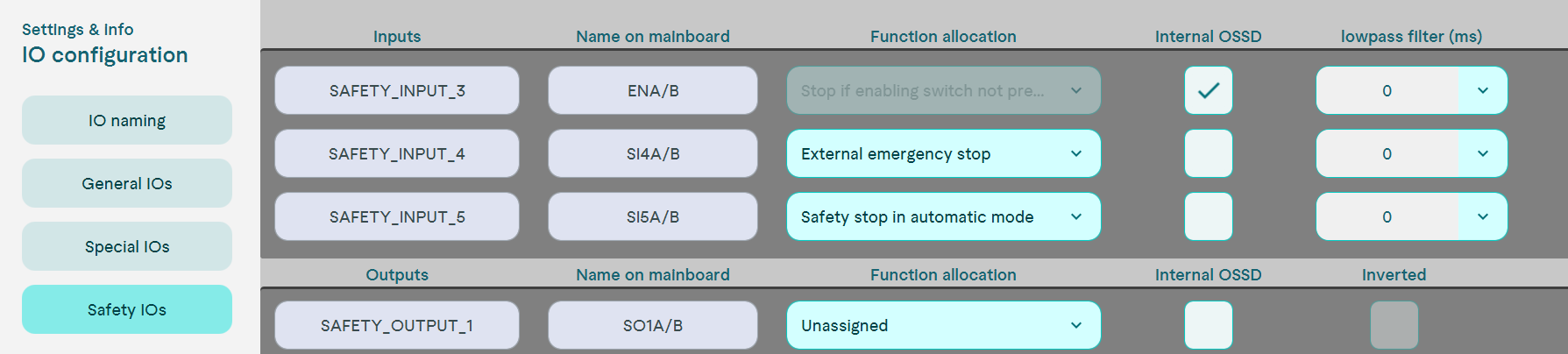
Configuring safety inputs
As the internal OSSD test signal is used via TA and TB, the “Internal OSSD” checkbox must be activated. The low-pass filter is therefore not necessary.

Configuring safety inputs in horstOS when using Internal OSSD TA/TB
Safety output signals for HORST
As on the input side, the output signals must also be configured in horstOS. The configuration can be found in horstOS under Project Setup > I/O configuration > Safety I/O. The following Table 1 describes the configuration of the safety outputs.
| **Output signal **HORST | Robot/Machine Tips: | Contact No. EUROMAP | Signal Description EUROMAP |
|---|---|---|---|
| SR5A1 SR5A2 | Configuration as “Forwarding emergency stop input” in horstOS *before version 2023.11 (emergency stop) | A1 | Emergency Stop of handling device (Channel1) |
| SR5B1 SR5B2 | Configuration as “Forwarding emergency stop input” in horstOS *before version 2023.11 (emergency stop) | A2 | Emergency Stop of handling device (Channel2) |
| SR6A1 SR6A2 | Configuration in horstOS as "two digital potential-free outputs" (Only necessary if MAF-contacts are not used with light curtain) | A3 | Mould Area free |
The following illustration shows the configuration interface in horstOS with the selected settings for the safety outputs.

Configuring safety output as an emergency stop
Once the inputs and outputs have been correctly assigned, the configuration must be saved. Only then will it be transferred to the control unit and become active.
In the user interface, the safety output Safety_Output_1 must be configured as “Forwarding emergency stop input”. Faults in the event of a robot crash do not lead to an emergency stop output signal, as this is generally not desired in injection molding processes.
For this application, it is otherwise possible to configure this signal with the “EMERGENCY STOP” function.
Once the inputs and outputs have been correctly assigned, the configuration must be saved. Only then will it be transferred to the control unit and become active.
A window with a list of all safety signals should then appear. Please check the settings in the list before finally saving the configuration.
All safety functions must be tested and finally checked during commissioning.
Use of Mould Area Free (MAF) release signal
The “Mould-Area-Free” signal MAF (A3-C3) serves as a release for a powerful movement of the mold. It must not be possible to close the mold when the robot is in the machine.
The signal can be integrated in several ways. Two options are described below. The recommendation is to integrate the signal via a light grid, which is the safest option for integrating the signal. Alternatively, the signal can also be switched as an output signal in the program.
Integration of a MAF light curtain
For this reason, a light grid is recommended as standard to check whether the mold is free. The light grid should be installed on the machine side as close as possible to the mold.
The interface is supplied without a light grid. A category 1 light grid is sufficient for the application (e.g. SICK automation light grid SLG-2, SLG50S-100SAR21A00). An additional coupling relay (e.g. PHOENIX 2903370 - RIF-0-RPT-24DC/21) is required for the connection. The integration of a light grid via a relay in Control is outlined in the following illustration.
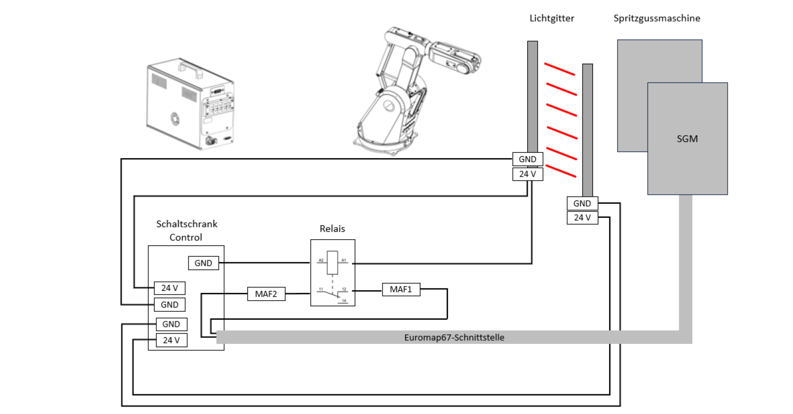
Schematic wiring diagram for connecting a light grid in the control cabinet via a relay
The light grid can be supplied with voltage from the Control switch cabinet. The contact on the light grid receiver side serves as a control signal for opening the relay. The potential-free contacts MAF1 and MAF2 of the Euromap67 interface, which are intended for the “Mould-Area-Free” function, can be used as normally open contacts for the relay.
The MAF input must always be HIGH when the light curtain is not blocked. As soon as the robot enters the machine, the release signal for mold closing is automatically interrupted.
The implementation of the “Mould-Area-Free” signal via the light grid is therefore independent of the program status and thus offers a safe implementation option.
Use of potential-free outputs as MAF signals
Alternatively, potential-free outputs can be used instead of a light grid, which switch the release for the injection molding machine on the program side.
MAF release
Caution! An error in the robot program could cause the mold of the injection moulding machine to close and crush the robot. This can damage both the robot and the mold.
The Control safety relays can be used to integrate the MAF signals via potential-free outputs. The signals are located on terminal block X8 (SR5 and SR6). As the SR5 outputs on the EUROMAP interface are assigned the emergency stop function as standard, the safety output signals SR6A1 and SR6A2 are provided for this purpose. The signals are described in the following table.
| **Output signa **HORST | Robot/Machine Tips: | Contact No. EUROMAP | Signal Description EUROMAP |
|---|---|---|---|
| SR6A1 SR6A2 | Configuration in horstOS as "two digital potential-free outputs" (Only necessary if MAF-contacts are not used with light curtain) | A3 | Mould Area free |
To be able to use the signal as a potential-free output, the Safety_Output_6 output must be configured as “Two outputs” in horstOS. The setting is made in horstOS in the settings under the menu as described in chapter 5: Configuration EAs > Safety EAs see the following figure:

Configuration of the MAF signal as a potential-free output in horstOS
Naming the inputs and outputs
In horstOS it is possible to name the inputs and outputs in such a way that they correspond directly to the names of the EUROMAP interface. A clearer naming of the inputs and outputs simplifies program comprehension and avoids programming errors.
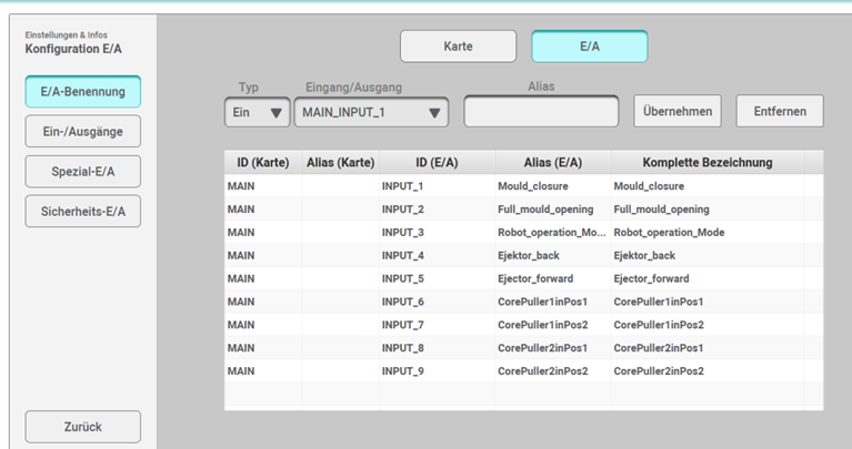
Naming the IOs in horstOS
Naming can be carried out using the signal descriptions from chapter 4.2. This means that the input and output signals are clearly named and can be used more easily in horstOS.
Example program for injection molding process
It is possible to use the prepared standard program as a template for an exemplary injection moulding process. Make sure that the safety settings and the injection molding machine are set correctly before starting programming and molding.
The standard program is based on the following injection moulding process.
- Reset all outputs (Output_Init)
- Start injection molding process
- Move core pulls 1 and 2 to Pos 1
- Close mold
- Reset core pulls 1 and 2 release
- Main program
- Wait until mold is open
- Move core pulls to Pos 2
- Pick (gripping the component)Move to component pre-position
- Extend ejector
- Gripping the component
- Extend SGM
- Retract ejector
- Start injection molding process
- Move core pulls 1 and 2 to Pos 1
- Close mold
- Reset core pulls 1 and 2 release
- Place (placing the part)
In the program sequence, the signals from the robot are only release signals for the injection moulding machine. The actual action (e.g. closing the mold) must be triggered by the SGM.
The following figure shows the program sequence in horstOS for an exemplary injection moulding process.
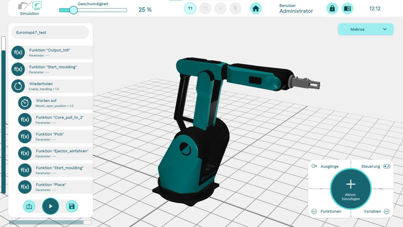
Program sequence in horstOS for an exemplary injection molding process
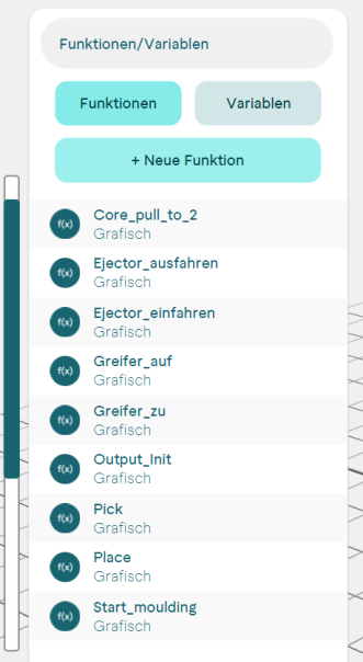
The commands and actions within the main program are largely outsourced to functions so that the main program remains clear. The following illustration shows the most important functions for an injection molding process.
Program example
Note: The outlined process is only a program example, which is intended to serve as a template for orientation. The program must therefore still be adapted for the respective process.
Importing the program template
The sample program is provided on a USB stick supplied. The program can be loaded directly from the horstOS programming interface.
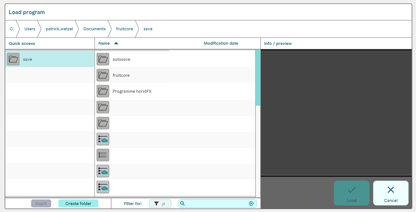
To integrate the program, click the “Load program” button in the horstOS main menu and then select the appropriate program from the USB stick. After selecting the correct robot model, the program is loaded.
Alternatively, the file can also be found under the following link: