
Determining the safety distance for electro-sensitive protective equipment
This procedure is explained using the MRB as an example, but it can be used with any product of this type.
Standards and guidelines
Caution!
The following information is provided without guarantee! Be sure to read and observe the applicable standards and guidelines in this context (e.g.: ISO 13855, 13857, 13854, 14120, 14119, etc.).
1 Use of non-contact protective devices
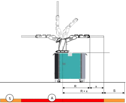 | A | Working area | ||
R | Range of the robot H600 = 584 mm H1000 = 1018 mm H1400 = 1425 mm H1500 = 1485 mm | |||
S | Safety distance of the protective fence to the work area | |||
x | maximum length | |||
The protective field of an electro-sensitive protective equipment must secure the hazard zone (working area A + safety distance S). DIN EN ISO 13855 – Arrangement of protective equipment with regard to approach speeds of parts of the body – applies for calculating the safety distance S.
If the manufacturer of the electro-sensitive protective equipment does not specify any other requirements, use the calculation bases on the following pages (see sections 8.1.1 and 8.1.2).
Stopping time T
The stopping time T of the entire system is an important characteristic for calculating the safety distance. It consists of:
t1 – response time (reaction time) of the protective device in seconds [s] (see documentation of the protective device manufacturer) and
t2 – stopping time of the robot system in seconds [s] (see MA Robot Systems HORST)
T = t1 + t2
Safety distance S
The minimum safety distance S to the robot's work area is generally calculated using the following equation:
S = (K × T) + C
S – minimum safety distance in mm
K – approach speed of persons in mm/s
T – stopping time of the entire system in s (see Section 8.1.1)
C – intrusion distance (safety margin)
Depending on the orientation of the protective field, the values for the approach speed K and the intrusion distance C vary. This is explained below.
1.1 Protective field at right angles to the approach direction
If the protective field is aligned at right angles to the approach direction (e.g. a vertically aligned light curtain), the following calculations apply:
When using an active optoelectronic protective device with sensor detection capability £ 40 mm, the following applies:
K = 2000 mm/s (according to DIN EN ISO 13855)
C = 8 × (d – 14) (according to DIN EN ISO 13855)
but not less than 0
d – sensor detection capability of the protective device in mm (minimum object resolution)
This results in the following for the minimum safety distance S:
S = (2000 mm/s × T) + C
This applies for a minimum safety distance S of up to and including 500 mm. The minimum value of S must be 100 mm.
If the calculated value for S exceeds 500 mm, the following equation can be used. In this case, the minimum value of S must be 500 mm.
S = (1600 mm/s × T) + C
If the sensor detection capability of the protective device is > 40 and £ 70 mm, the following applies:
K = 1600 mm/s (according to DIN EN ISO 13855)
C = 850 mm (according to DIN EN ISO 13855)
This results in the following for the minimum safety distance S:
S = (1600 mm/s × T) + 850 mm
Example calculation for a protective field perpendicular to the approach direction
When using a safety light curtain with the following output values:
t1 = 0.2 s – response time (reaction time) of the protective device
t2 = 0.53 s – stopping time of the robot system
d = 60 mm – sensor detection capability
results in the stopping time T:
T = 0.2 s + 0.53 s
T = 0.73 s
and thus the minimum safety distance S to the work area:
S = (1600 mm/s × T) + 850 mm
S = (1600 mm/s × 0.73 s) + 850 mm
S = 1168 mm + 850mm
S = 2018 mm
The protective field of the safety light curtain must be configured so that the entire hazard zone (i.e. the operating range + safety distance S) is safeguarded.
1.2 Protective field parallel to the approach direction
If the protective field is aligned parallel to the approach direction (e.g. a horizontally aligned safety laser scanner), the following calculations apply:
K = 1600 mm/s (according to DIN EN ISO 13855)
C = 1200 mm – 0.4 × H (according to DIN EN ISO 13855)
but not less than 850 mm, where H is the height of the protective field (in mm) above the floor
This results in the following for the minimum safety distance S:
S = (1600 mm/s × T) + (1200 mm – 0.4 H)
The height H of the protective field must not exceed 1000 mm. According to EN ISO 13855, for protective field heights greater than 300 mm, the possibility that the protective field can be crawled under must be taken into account.
The lowest permissible height H of the protective field is calculated in the following equation:
H = 15 × (d – 50)
d – sensor detection capability of the protective device in mm (minimum object resolution)
If d is smaller than 50 mm, H must never be set to zero.
Thus, for a fixed height H of the protective field, the equation for the sensor detection capability d of the protective device is obtained:
d = (H/15) + 50
The sensor detection capability d (minimum object resolution) of the protective device must then be configured.
When using safety laser scanners, it must be taken into account that scanner measurement errors and errors due to a reflective background can occur. To take these errors into account, an additional safety value Z is added to the minimum safety distance S.
S = (K × T) + C + Z
This safety value Z can vary between 60 and 200 mm. The corresponding information can be found in the scanner manufacturer's documentation.
Example calculation for a protective field parallel to the approach direction:
When using a safety laser scanner on the MRB with the initial values:
t1 = 0.2 s – response time (reaction time) of the protective device
t2 = 0.53 s – stopping time of the robot system
H = 300 mm (at d = 70 mm)
the stopping time T is obtained:
T = 0.2 s + 0.53 s
T = 0.73 s
and thus the minimum safety distance S to the work area:
S = (1600 mm/s × T) + (1200 mm – 0.4 H)
S = (1600 mm/s × 0.73 s) + (1200 mm – 120 mm)
S = 1168 mm + 1080 mm
S = 2248 mm
The protective field of the safety laser scanner must be configured so that the entire hazard zone (i.e. the working range + safety distance S) is safeguarded.