Component Kit modular robot fence
General Guidelines
Note
This document serves as a helpful guide for assembling the Component Kits. Please note that it is not a complete installation manual in the traditional sense.
Safety notice
Seek professional assistance if necessary to avoid dangerous situations and injuries.
Assembly Parts
| No. | Designation |
|---|---|
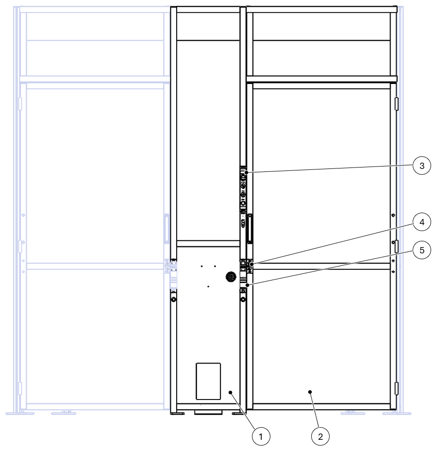
| 1 | Robot fence base element |
| 2 | Robot fence door element |
| 3 | Control console |
| 4 | Actuator |
| 5 | Locking |
| 6 | Cable entry |
| 7 | Safety control cabinet |
| 8 | Connection cable Robot control cabinet |
| 9 | Mounting plate Robot control cabinet |
| 10 | Screwing points Control panel holder |
Front view :
**
Rear view :
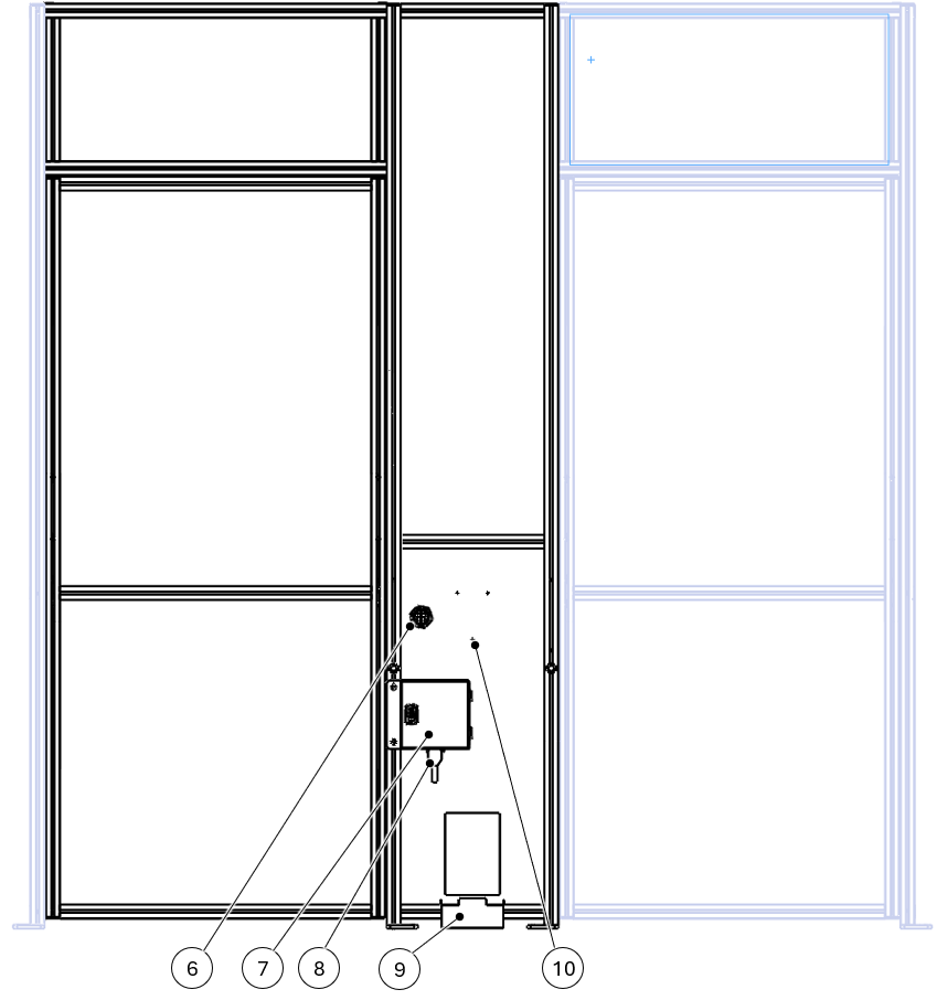
BILD Long and short module, connecting elements --> or omission in Bertschinger instructions?
Required Tools
- Hex key 2.5mm, 4mm, 5mm
- Open-end wrench 8mm
- Flat-head screwdriver
Assembly steps
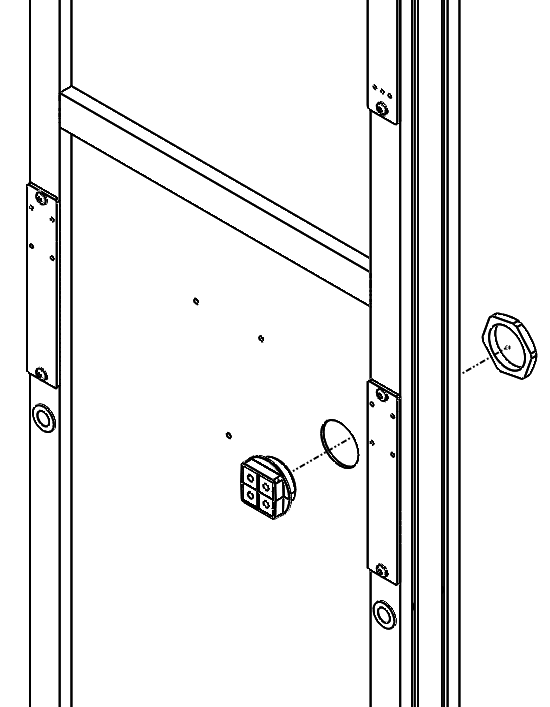
The divisible cable entry for the control panel cable is screwed into the cover of the base element (hole Ø25.2) using the M25 lock nut.
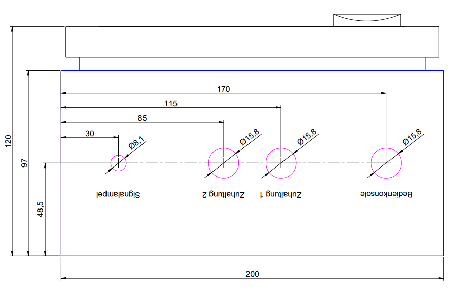
The control panel is screwed onto the upper mounting plate using 6x cylinder head screws DIN 7984 M4x8. The guard lock is screwed onto the lower mounting plate using 4x cylinder head screws DIN 912 M5x20. Depending on whether the door(s) are on the right, left or both sides of the base element, the guard lock(s) are mounted on the corresponding mounting plate. The mounting holes for the guard lock are then closed using the enclosed blind plugs and the supplied signal cable is screwed into the M12 socket.
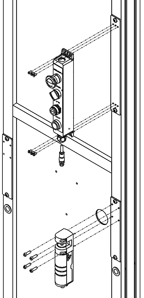
The signal cables for the control panel and the guard lock(s) are fed through the respective openings in the aluminum profile and plugged into the labeled M12 connection sockets on the top of the safety control cabinet and screwed into place.
The safety control cabinet is mounted on the back of the base element in the groove of the left aluminum profile. The screw connection is made with 2x lens head screws ISO7380 M8x14 and 2x slot nuts 8I M8 through the mounting plate into the profile groove, the lower edge of the control cabinet is positioned approx. 500mm above the floor. The support plate of the robot control cabinet is screwed with the same components in the middle of the profile groove of the lower aluminum profile.
The height of the sheet support can be adjusted to the floor using the elongated holes.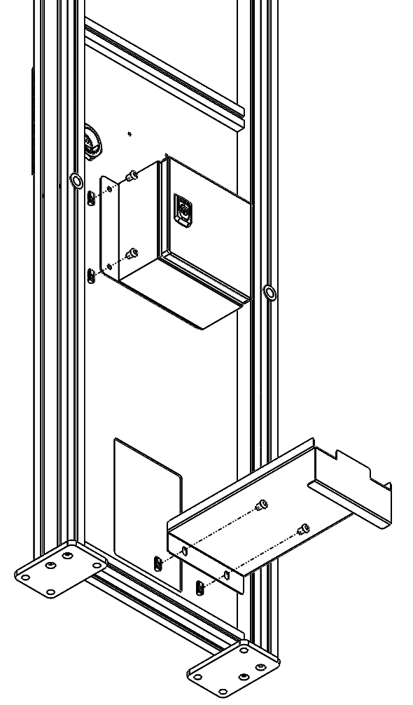
The actuator of the guard locking device is screwed to the door's mounting plate using 2x cylinder screws DIN7984 M5x8 and the mounting holes are then closed with the enclosed blind plugs.
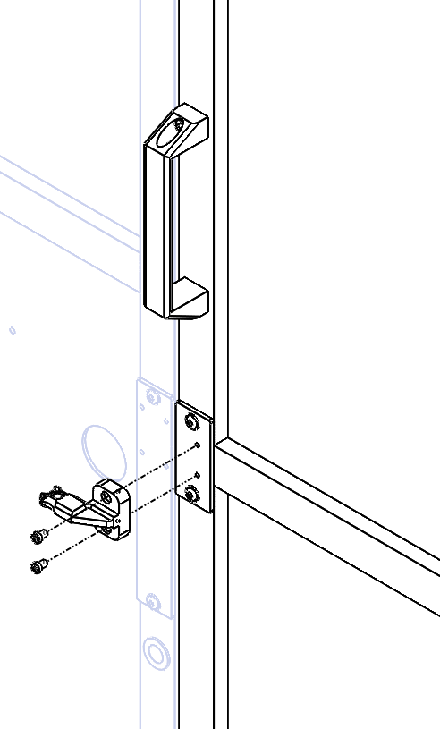
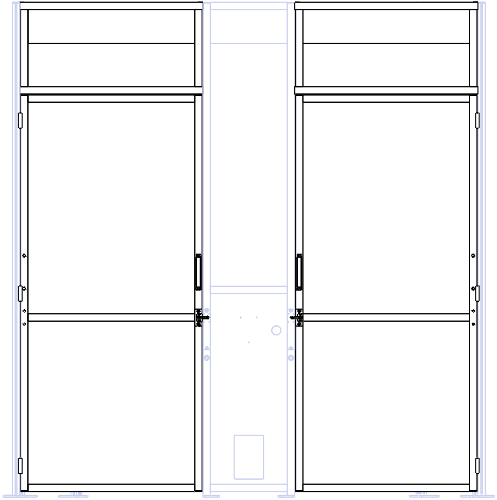
The mounting position of the mounting plate for the actuator as well as the door handles and the hinges can be flexibly set to the left or right for the door position on both sides of the robot base. The mounting holes that are not used are closed with the enclosed blind plugs.
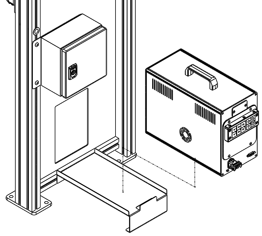
- The robot control cabinet is positioned onto the mounting plate and fastened securely using the provided tensioning belt.
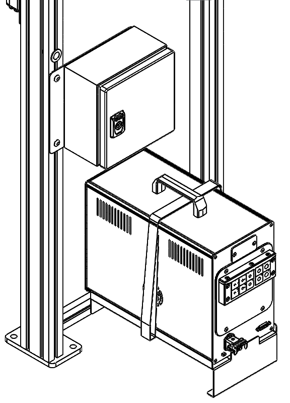
The connection cable from the safety control cabinet to the robot control cabinet is plugged into the Sub D socket on the underside of the safety control cabinet.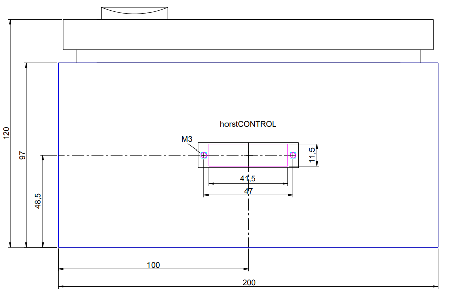
The pluggable connection blocks are plugged into the I/O interface of the robot control cabinet according to the terminal designation (X1, X2, ...). 6. The panel holder is mounted on the cover of the base element using the included mounting set (3x cylinder head screw DIN 912 M5x16, 3x washer DIN 125 M5, 3x nut DIN 985 M5).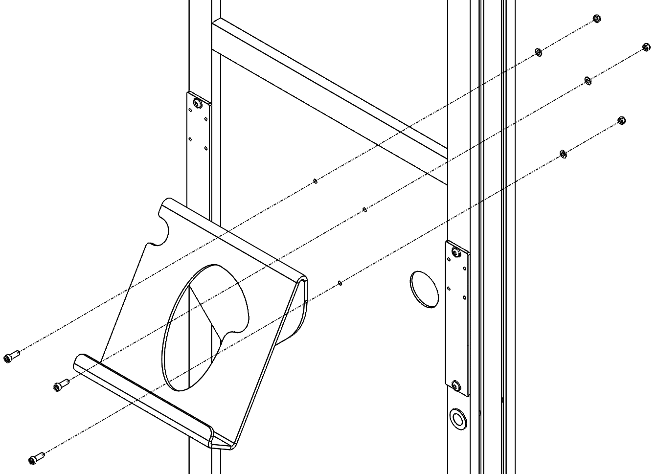
After setting the control panel in the holder, the control panel cable is fed through the separable cable gland and plugged into the robot control cabinet.
Wiring plan Safety control cabinet
The following table shows the standard I/O assignment of the connection cable to the robot control cabinet, as well as the corresponding function assignment in horstOS/FX:
Clamp | I/O | Description | Function assignment horstOS /FX |
X1.1 | DI01 | Begin | Program start |
X1.2 | DI02 | Continue | program continue |
X1.3 | DI03 | Break | program pause |
X1.4 | DI04 | Door request | Optional: Program pause |
X1.5 | DI05 | Locking 1 OK | - |
X1.6 | DI06 | Locking 2 Ok | - |
X5.1 | SI4A | OSSD locking 1 | Safety stop in the Automatic mode |
X5.2 | SI4B | ||
X5.3 | SI5A | OSSD locking 2 | Safety stop in the Automatic mode |
X5.4 | SI5B | ||
X7.1 | SO1A | robot stopped for locking | robot stopped |
X7.3 | SO2A | Signal light green | Two digital outputs + program running |
X7.4 | SO2B | Signal light yellow | Two digital outputs + program paused |
X7.5 | SO3A | Signal light red | Two digital Outputs + Errors |
X6.1 | TA | Emergency stop control console | Internal Emergency stop |
X6.2 | EIA | ||
X6.3 | TB | ||
X6.4 | EIB | ||
X14.1 | GND | GND | - |
X12.1 | 24V | 24V | - |
The complete wiring plan of the safety control cabinet can be found at the following link:
Wiring plan Safety control cabinet
The cable drawing of the robot control cabinet connection cable can be found under the following link:
Cable drawing Connection cable Safety control cabinet
Assembly of the fence elements
The following sections describe how to connect short, long, door and base elements using 90°, 180° and adjustable connections.
Adjustable field
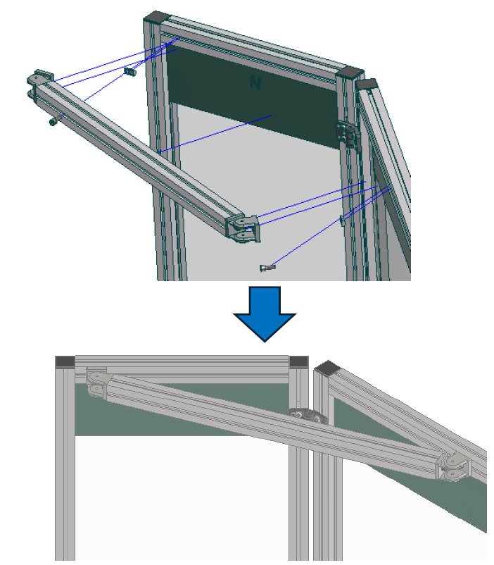
Required kit: special-angle connections other than 90°. The kit comprises 3 hinges for internal mounting with fasteners, 2 floor plates 90x90 with floor anchors and 1 diagonal aluminium-profile brace 40x40 with 2 joints.
Replace the preassembled floor plates on the adjustable-angle side with 2 floor plates 90x90. Remove the galvanised socket-head screw DIN7984 M8x30 from the floor plate 140x90 and use it to install the floor plate 90x90.
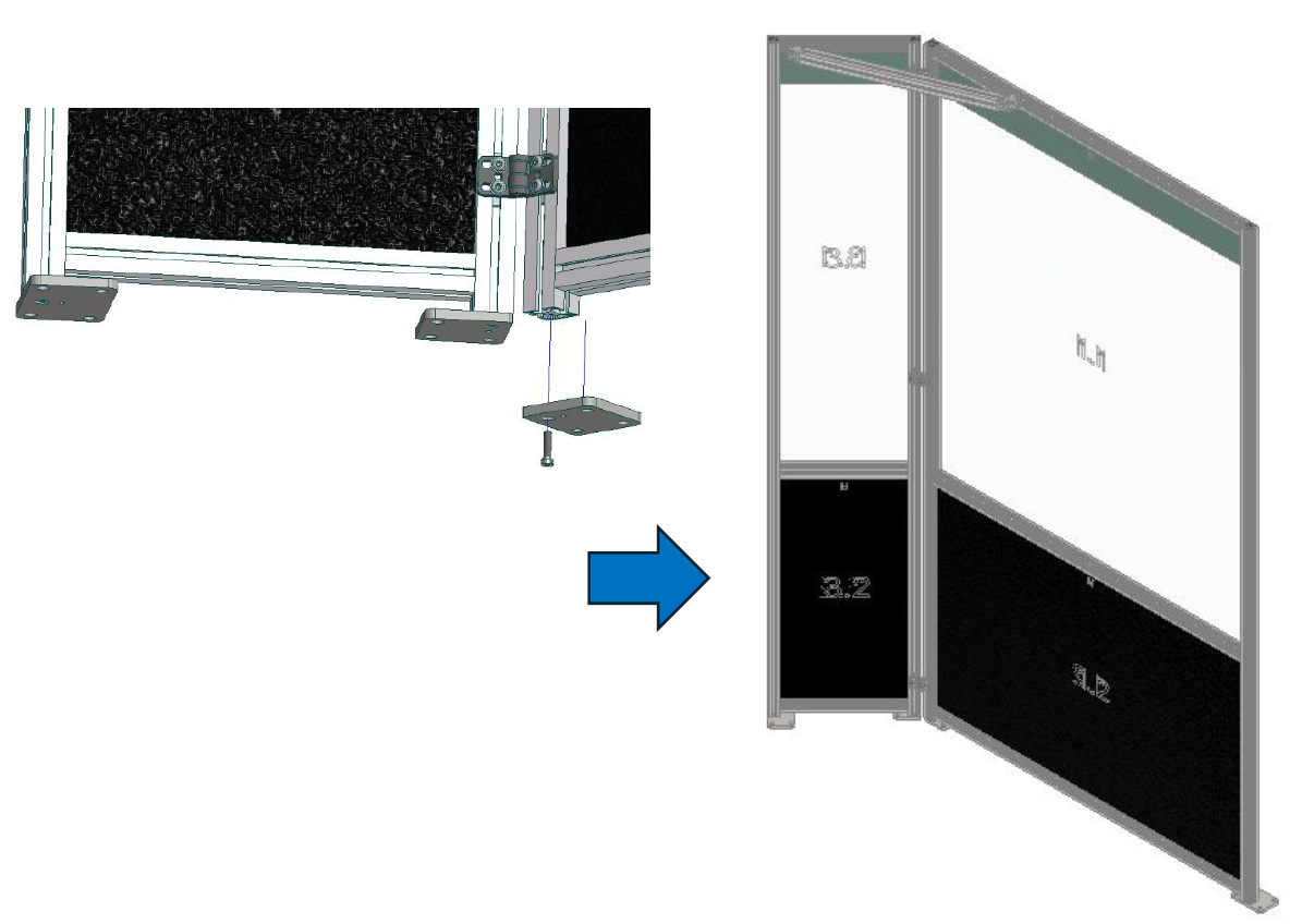
Mount the hinges on the inside of the fields using 4 flange button-head screws ISO7380 M8x20 and 4 slot-8 M8 nuts in the rear profile slot.
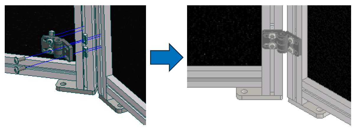
After setting the required angle, install the diagonal brace. Remove the slot-8 M8 nuts from the joints, swivel them into the rear field slot and secure the brace with socket-head screws DIN912 M8x20.
180° connection
Required kit: straight connections, comprising 4 connection plates with fasteners.
For a 180° connection, rotate the floor plates by 90°.
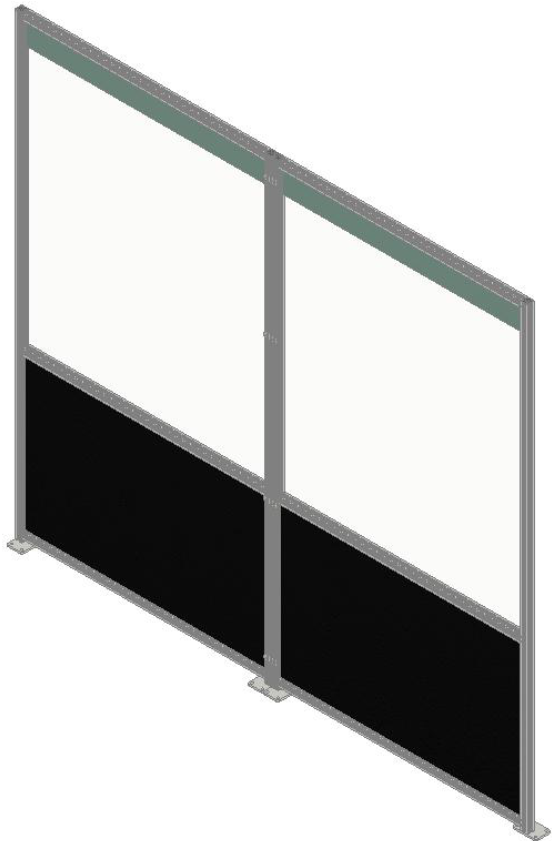
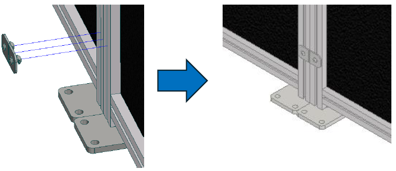
Install the preassembled 76x35 mm plates on the inside of the protective enclosure at approximately equal intervals. Use flange button-head screws ISO7380 M6x14 and galvanised hammer nuts N8-40 M6.
180° connection beside the base field
No separate kit is required; the necessary corner elements are supplied with the base field. If necessary, rotate the floor plate at the joint to the base field by 90°.
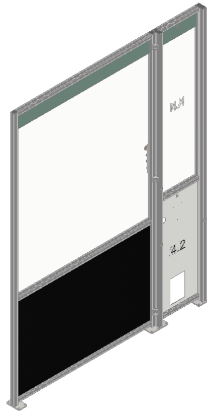
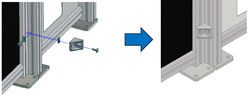
Mount the field to the base field using three 40x40 corner elements. Swivel the slot-8 M8 nut into the slot and secure the 38x38 corner bracket with a flange button-head screw ISO7380 M8x20.
Diagonal braces
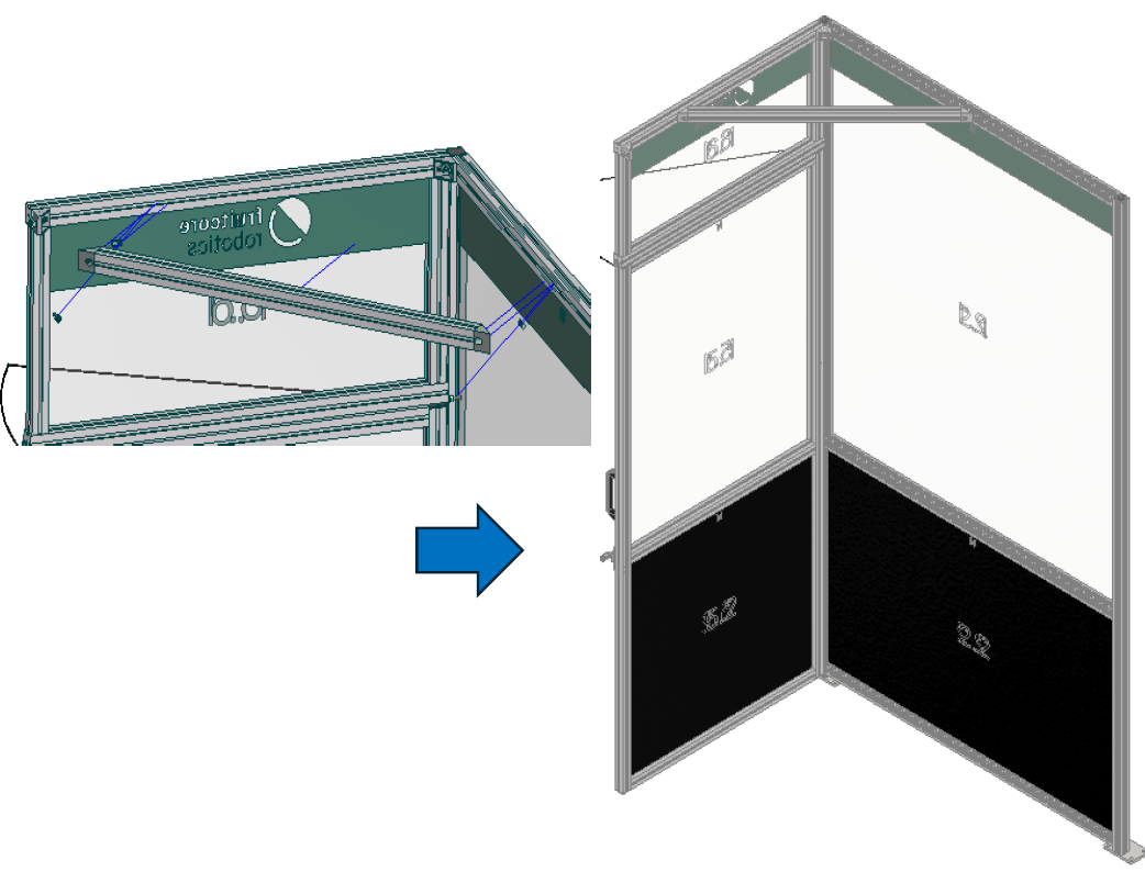
Required kit: diagonal braces, comprising an aluminium profile 40x40, 2 corner elements 45° and fasteners.
The brace stiffens 90° connections. Remove the slot-8 M8 nuts from the 45° corner elements, swivel them into the inward-facing profile slot and mount the brace with socket-head screws DIN912 M8x20.
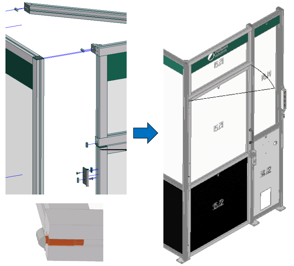
Door element
To mount the protective field above the door (1000 x 500 mm), screw the upper cross profile to the adjacent fields using corner elements. Secure the lower cross profile with thread-form connectors: swivel each connector nut into the slot of the adjacent field, then screw the hexagon-socket screw into the nut. Swivel the nuts of the lower door-hinge leaves into the adjacent field slot and secure the leaves at the height required by the door.