
Component Kit SICK laser scanner microScan PRO IO
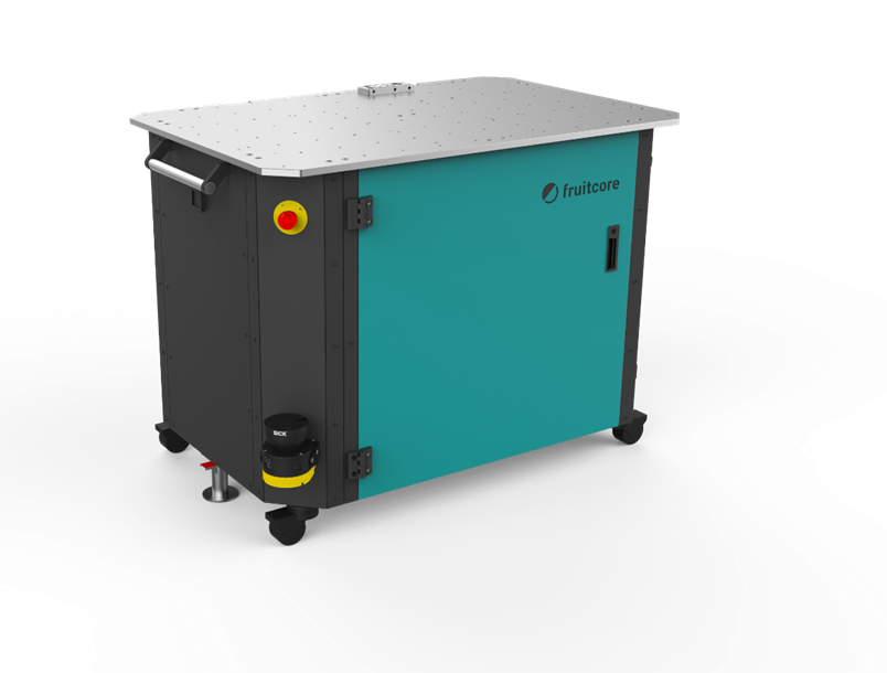
This article is valid for all horstOS versions, as well as for all horstFX versions.
General information
Note
This document is intended solely as support for the installation of the safety scanner on the MRB. This document is not an installation guide in the true sense of the word. The document describes the connection of the scanner to Control with new mainboard (delivered from January 2022).
Safety notice
Obtain professional assistance if necessary to avoid dangerous situations and injuries
Power supply
Switch off the robot system before carrying out the following steps. As soon as all steps have been carried out, the electrical power supply may be switched on again
Informationen on the product SICK Laserscanner microScan3 PRO
The data sheet and other documents and information for the microScan3 Pro I/O can be found at the sick homepage.
The direct link is
https://cdn.sick.com/media/docs/3/83/183/operating\_instructions\_microscan3\_pro\_i\_o\_safety\_laser\_scanner\_de\_im0098183.pdf — source file currently unavailable; request the matching version from the manufacturer
The technical documentation and dimensions can be found at www.sick.de under the designation "Mounting kit 2a" or "Mounting kit 1b" or under order number 2073852 or 2074242.
The direct links are as follows:
Kit 1b: https://www.sick.com/de/de/befestigungssatz-1b/p/p422150
Mounting parts
| No | Quantity | Description |
|---|---|---|
| 1 | 2 | M5x16 countersunk head screw with hexagon socket, DIN 7991 |
| 2 | 2 | M5 nut with threadlocke, DIN 985 |
| 3 | 2 | Washers M5, DIN 125 |
| 4 | 4 | M5x8 countersunk head screw with hexagon socket, DIN 7991 |
| 5 | 1 | SICK laser scanner |
| 6 | 1 | Connection cable 24V |
| 7 | 1 | Connection cable |
| 8 | 1 | Spacer |
Tools required
- Allen key 5 mm
- Open-end spanner 7 mm
Procedure
Step 1: Mounting the safety scanner on the MRB
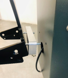
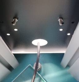
The first step is to screw the laser scanner to the intended mounting option on the MRB. Please refer to the information in the operating instructions for the MRB.
Mounting bracket with M5x16 countersunk screw (view from outside)
Mounting bracket with M5 nut with screw lock (view from inside)
Fixing the scanner to the holder
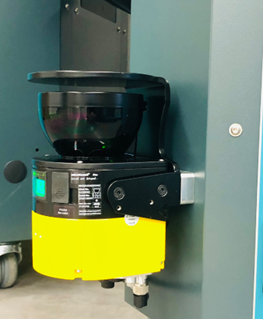
Step 2: Electrical installation and cabling
Once the laser scanner has been successfully attached to the MRB, the electrical installation can now be carried out. To do this, connect the pre-assembled cables to the mainboard according to the labelling on the connectors.
Power is supplied to the device via a 4-pin, A-coded M12 connector:
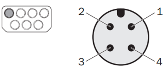
The pin assignment is shown in the following table:
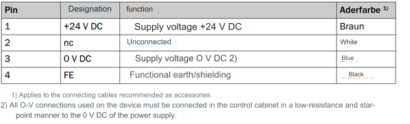
The following table describes the connection of the cable to HORST:
| Pin | Colour | Cable Description | HORST |
|---|---|---|---|
| 1 | brown | Supply voltage 24V | Power 24 V (red area) |
| 2 | n.b. | not used | |
| 3 | blue | Supply voltage 0V DC | Power GND (red area) |
| 4 | n.b. |
The local inputs and outputs are connected on the device side via 17-pin, A-coded M12 sockets. If both 17-pin connections are used, both 17-pin cables must be clearly labelled to prevent confusion when replacing the device.
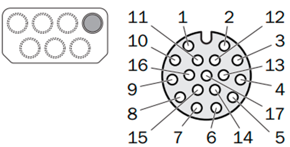
Pin assignment of local inputs and outputs 1 (socket, M12, 17-pin, A-coded)
The assignment of pin, designation, function and wire colour can be found in the connection table (see Table 2). This requires the use of standard cables from SICK (type: YN2A1D-100UV1XLEAX, item no.:2118011, https://www.sick.com/de/de/yn2a1d-100uv1xleax/p/p671027).
The connection cable on the scanner side is described in the BA of the scanner.
Connection table 17-pin signal cable to Control
| Pin | Colour | Description | HORST | Configuration horstOS |
|---|---|---|---|---|
| 1 | brown | OSSD1A | SI4A | Safety stop |
| 2 | blue | OSSD1B | SI4B | Safety stop |
| 3 | white | OSSD2A | SI5A | Error if speed not reduced |
| 4 | green | OSSD2B | SI5B | Error if speed not reduced |
| 15 | white-yellow | universal output1 | DI1 | Reduced speed (triggering) |
| 17 | white-grey | Supply 0V | GND HORST |
The following steps must be carried out to wire the SICK Control safety system:
connect OSSD 1A (brown) to Safety Input SI4A HORST (+)
connection OSSD 1B (blue) to Safety Input SI4B HORST (+)
connection OSSD 2A (white) to Safety Input SI5A HORST (+)
connection OSSD 2B (green) to Safety Input SI5B HORST (+)
connection Universal I/O 1 (white-yellow) to Digital In HORST (+)
connection 0V DC (white-grey) to GND HORST (-)
the remaining cables are not wired
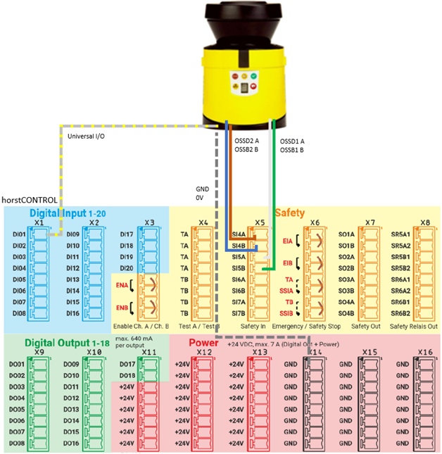
Wiring diagram Scanner microScan3 PRO to Control
SSIA and SSIB on terminal X6 can also be used for the automatic safety stop triggered by OSSD1. All other safety inputs of terminal X5 (SI4 to SI7) can also be used if they are configured accordingly in horstOS.
In the example above, the inputs SI4 and SI5 are used as an example. The configuration for this is described in detail below.
Pin assignment on the Control switch cabinet
The following figure shows a possible wiring of the safety scanner to Control.
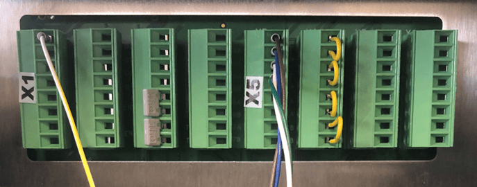
Connection of OSSD-1 and OSSD-2 and Universal IO on the Control switch cabinet
The PowerOut 24V connections on X12 and X13 can be used for the supply voltage in the same way as when using only one safety scanner. The terminals on X14, X15 and X16 can be used for the GND ground. The connection of the signals is shown in the following illustration.
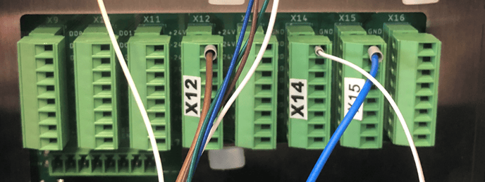
The connection diagrams at the control cabinet are shown in chapter 3.3.
Configuration of the safety stop inputs
To do this, navigate in horstFX to Settings > Configuration I/O > Safety I/Os. or in horstOS to Project Setup > Configuration I/O > Safety I/Os.
Configure the safety input SAFETY_INPUT_2 and set a low-pass filter of 5 ms. This is necessary to ensure that the external OSSD signal from the safety scanner is filtered correctly.
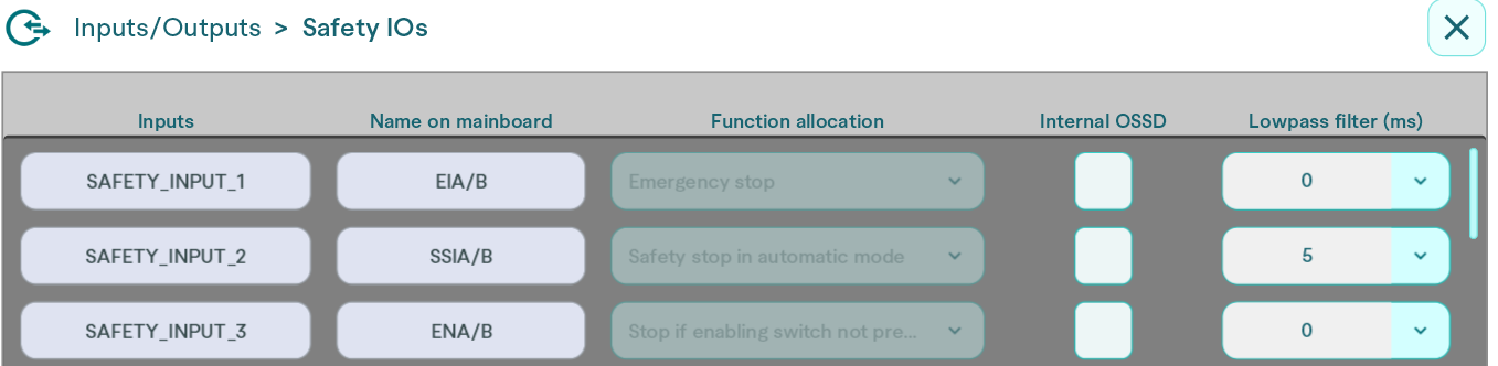
Configuration of the safety inputs in horstOS
In addition, the digital input INPUT_1 must be configured as “Reduced velocity”.

Configuration of the digital input in horstOS
Configuration of the safety scanner in the SICK Safety Designer
In the next step, the safety scanner is configured on the software side and the required safety ranges are set. These safety areas depend on the other safety devices that are used in combination with the scanner.
The entire setup and configuration of the laser scanner is described in the operating instructions for the safety scanner. Information on the detailed procedure can be found in the operating instructions for the microScan3 Core I/O from SICK or by downloading the following PDF:
https://cdn.sick.com/media/docs/3/83/183/operating\_instructions\_microscan3\_pro\_i\_o\_safety\_laser\_scanner\_de\_im0098183.pdf — source file currently unavailable; request the matching version from the manufacturer
Only the points that are important for the HORST installation are described below. As a project template, you can download a Safety Designer project template in the Peripherals section of horstCOSMOS.
https://horstcosmos.com/documentation/Peripheriegeräte
Application-specific safety settings
The safety settings must be individually adapted to the current working environment. The project template therefore only serves as an aid, but the settings and protective fields must be adapted to the application on a project-specific basis.
Please note that the integrator is responsible for integrating the scanner; these instructions only serve to connect the scanner to the HORST interface.
- Connecting the safety scanner to a laptop via the micro USB cable for setup
- Open the SICK Safety Designer app to configure the safety scanner
- Create a new project (see project template in horstCOSMOS.com)
- Connecting the scanner
Configuring the scanner and setting up the new device
Execute the Readout, Identification, Application and Monitoring level steps (see BA SICK)
Definition of the monitoring level. Depending on the setting, the values influence the required safety distance (see BA SICK and standards EN ISO 13855 and 13857).
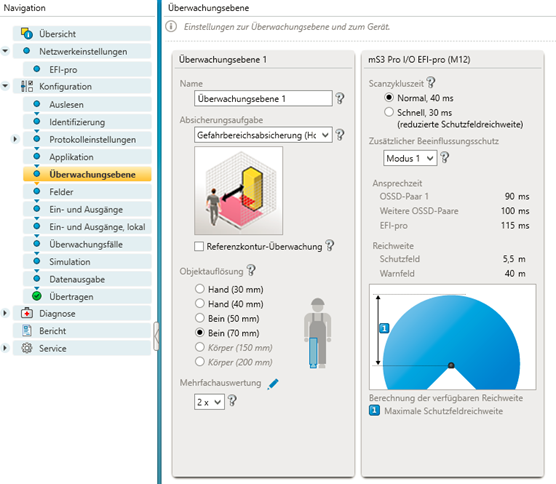
Settings for the monitoring level and the deviceCreating the protective fields:
These must be calculated using the standards for safety distances EN ISO 13857 and 13855 (see also BA SICK) and the robot's stopping times (see BA HORST).
Two field sets with the protective field type must be created. The outer field is used to monitor the reduced speed. The inner one leads to a safety stop of the robot.*
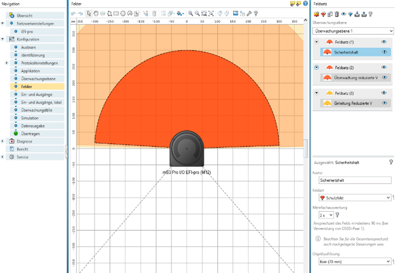
Creating the protective fields*
- Create the warning field:
When the warning field is reached, the robot's reduced speed is initiated. This must happen before it is monitored as a protective field. This area is not redundant and is therefore initiated with a simple digital input of the robot.
- Definition of inputs:
No scanner inputs are required for the standard configuration.
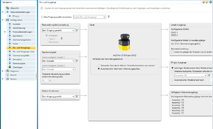
*Definition of the scanner inputs*
Definition of the inputs and outputs, locally
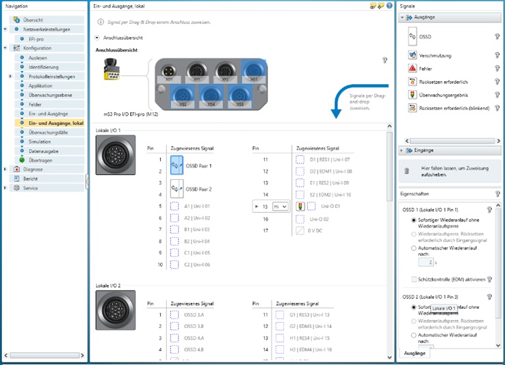
Definition of local inputs and outputs- Connection of pin 1 for the power supply (24V) and pin 3 for the ground GND (0V)
- Connection of OSSD pair 1 for the protective field (PIN 2 and pin 4)
- Connection of universal output pin 5 and set to Low
- Assign the warning light as a monitoring result using drag and drop
Create the monitoring cases:
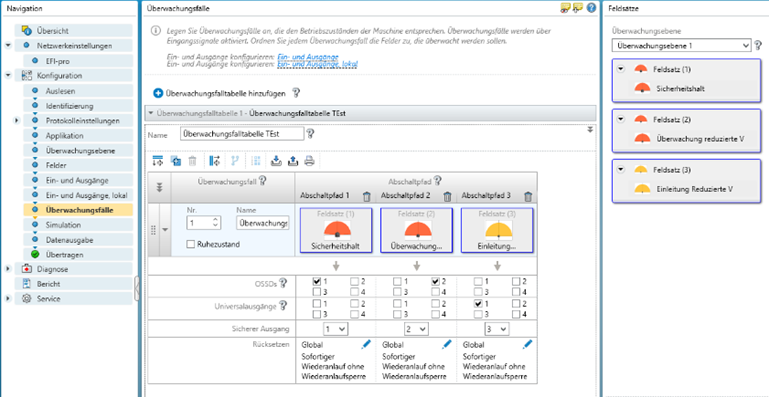
Monitoring cases
-   Protective field Field set assignment for OSSD pair 1 (redundant safety-relevant)
-   Warning field Field set for assignment of universal output UO1 (simply wired, therefore not safety-relevant!)
- Simulation and transfer to the device.
- Creation of the project safety report for the safety documentation of the safety cell (CE).