
Component Kit SICK laser scanner nanoScan3 PRO IO
General Guidelines
Note
This document serves as a guide for installing the security scanner on the MRB. It is not a traditional installation manual but rather provides instructions for connecting the scanner to Control with a new mainboard (shipped from January 2022).
Safety notice
Seek professional assistance if necessary to avoid dangerous situations and injuries.
Power supply
Before starting the assembly steps, make sure to power off the product. Once all assembly steps are completed, you can safely turn the power back on.
Product Information for SICK Laserscanner nanoScan3 PRO IO.
For the data sheet and other documents and information regarding the nanoScan3 PRO IO, please visit the website www.sick.de. Search for the designation AAAZ40AZ1P01 or order number 1075842 in the search field.
The direct link is:
The laser scanner includes a mounting kit for installation. The NS3 MOUNTING KIT 2B not only serves as a mounting solution but also acts as a protective enclosure for the scanner. You can find the technical documentation and dimensions on the website www.sick.de under the designation "NS3 MOUNTING KIT 2B", which is linked to order number 2111770.
Mounting Parts
| Nr | Quantity | Designation |
|---|---|---|
| 1 | 1 | SICK-Laserscanner |
| 2 | 1 | Connector |
| 3 | 4 | M5x8 Countersunk screws with hexagonal socket., DIN 7991 |
| 4 | 2 | Washers M5, DIN 125 |
| 5 | 2 | M5x16 SCountersunk screw with hexagonal socket, DIN7991 |
| 6 | 2 | Nut M5 with screw lock, DIN 985 |
| 7 | 1 | Connection cable |
| 8 | 1 | MOUNTING KIT 2B |
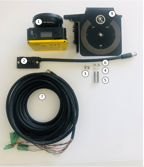 Tools required
5mm hex key
7mm open-end wrench
Procedure:
Step 1: Installing the safety scanner on the MRB
In the first step, attach the laser scanner to the designated mounting location on the MRB. Refer to the operating manual for the MRB for detailed instructions on this step.
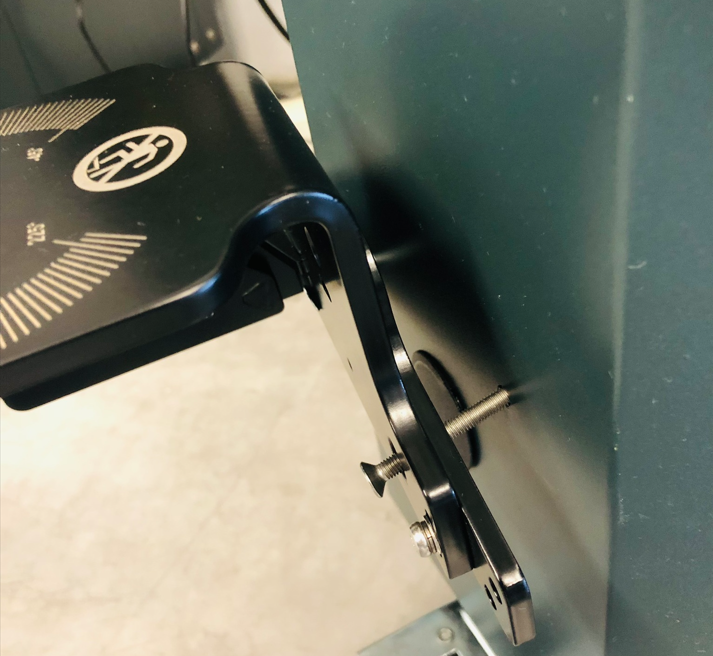
Attach the bracket using M5x16 countersunk screws (view from the outside).
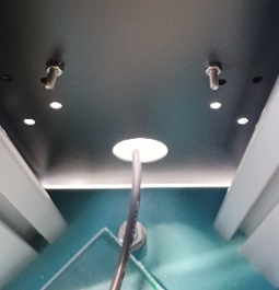
Mounting bracket with M5 nut and screw lock (view from the inside)
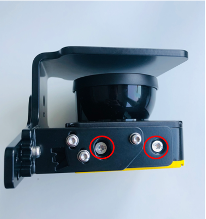
Attaching Scanner to Bracket
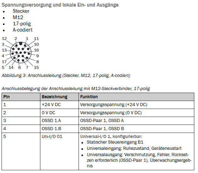
After successfully attaching the bracket to the MRB, proceed to connect the connector to the laser scanner. Connect the pre-assembled cable to the connector and match the markings on the connectors to the mainboard of the control cabinet (refer to the "Connection Plan microScan3 to Control" diagram). You can refer to the connection table for pin assignment, labeling, function, and wire color details.
Configuration of Safety Inputs
To configure the safety inputs, open horstFX and navigate to Settings > IO Configuration > Safety IOs
In horstOS navigate to "Project Setup > In- / Outputs > Safety- I/Os".
Configure the safety input SAFETY_INPUT_2 by setting a 5 ms low-pass filter. This filter is necessary to accurately filter the external OSSD signal from the safety scanner.
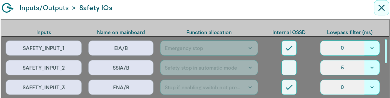
Configuration of the Safety inputs
Additionally, the digital input INPUT_1 has to be set as „reduced velocity“ konfiguriert werden.

Configuration of the digital input
Detailed illustrations of the connections at the Control cabinet can be found in Chapter 3.3 of the manual as a visual representation.
Configuration of the safety scanner
The complete setup and configuration of the laser scanner is detailed in the operational manual of the safety scanner. For a step-by-step guide, refer to the user manual for the microScan3 Core I/O by SICK or download the PDF from the following link:
https://cdn.sick.com/media/docs/4/54/754/operating_instructions_microscan3_core_i_o_de_im0063754.pdf
The following points describe what is important for the HORST-side installation.
Please note that the integration of the scanner is the responsibility of the integrator. This guide is only for connecting the scanner to the HORST interface.
- Connecting the safety scanner via the Micro-USB cable to a laptop for setup.
- Open the SICK Safety Designer App to configure the security scanner.
- Creating a new project (Alternatively: Use a project template, request from fruitcore)
- Connecting the scanner
 5. Download the configuration file from the USB stick provided and transfer it to your scanner.
Configuring the scanner and setting up the new device
On the attached USB stick, you will find a pre-configured setup file. After transferring this file, only adjustments to the protection fields are required (Step 2)..
If you prefer to configure it yourself, follow these steps.
- Following the steps of reading, identification, application, and monitoring level (refer to SICK manual)
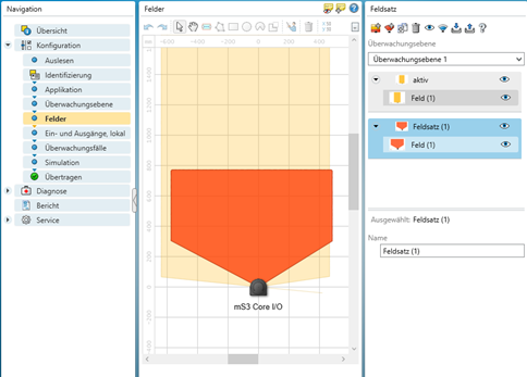
- Create the protective fields. Calculate them using the safety-distance standards EN ISO 13857 and EN ISO 13855 (see the SICK operating instructions) and the robot stopping times (see the HORST operating instructions).
- Creating warning fields allows for reduced speed operation within them, serving as an additional warning function. Since this function is not redundantly executed, it does not diminish the protective field.
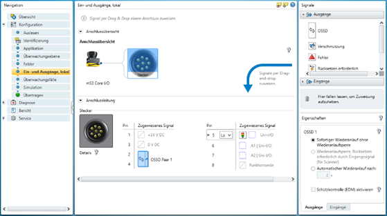
- Setting up the inputs and outputs locally
- Connect Pin 1 for power supply (24 V) and Pin 3 for ground GND (0 V).
- Connecting the OSSD pair 1 for the protective field (PIN 2 and Pin 4)
- Connect Pin 5 of the universal output and set it to low.
- Assign the warning light as a monitoring result by dragging and dropping.
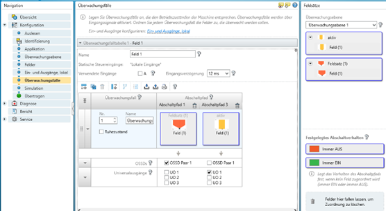
5. Creating monitoring cases
- Protective field setting assignment for OSSD pair 1 (redundantly safety-critical)
- Warning field setting for assigning the universal output UO1 (single-wired, therefore not safety-critical!)
6. Simulation and transferring to the device
- Creation of the project safety report for the safety documentation of the safety robot cell (CE)