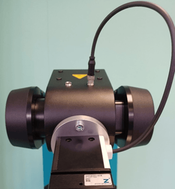
Component Kit Zimmer GEP2010IO-00-B
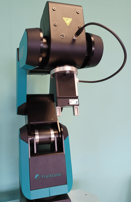
General Guidelines:
Note
This document serves as a helpful guide for assembling the Component Kits. It does not provide a step-by-step installation manual in the traditional sense.
Safety notice
Seek professional assistance if necessary to avoid dangerous situations and injuries.
Power supply
Before starting the assembly steps, make sure to turn off the power to the product. Once all assembly steps are completed, you can safely turn the power back on.
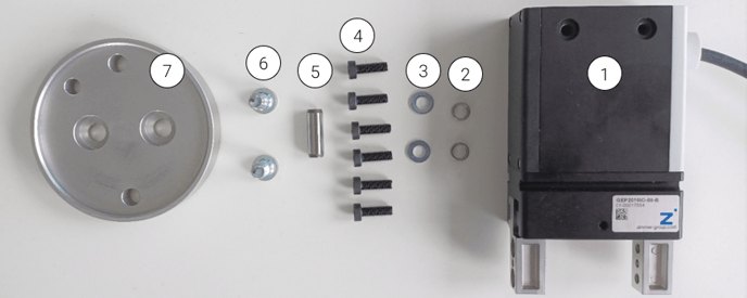
Assembly Components
| Nr | Quantity | Description |
|---|---|---|
| 1 | 1 | Electric Gripper Zimmer GEP2010IO-00-B |
| 2 | 2 | Adapter sleeve for Gripper to Adapter 7x3 mm |
| 3 | 2 | Washers DIN 9021 4.3x12x1.00 |
| 4 | 6 | Cylinder screw DIN 7984, M4x12 (low head) |
| 5 | 1 | Centering pin 6x14 M6 |
| 6 | 2 | Cylinder screw DIN 6912, M6x12 |
| 7 | 1 | Adapter plate for Zimmer GEP2010IO-00-B |
Required Tools:
- Allen key sizes of 2.5mm and 5mm are required for the assembly process.
Procedure
Insertion of the centering sleeves and mounting of the adapter plate on the gripper.
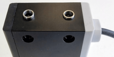
To ensure a centered assembly of the adapter plate onto the Gripper Zimmer GEP2010IO-00-B, start by inserting the centering sleeves (7x3mm centering sleeve) into the holes of the gripper housing.
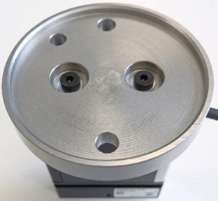
Next, press the adapter plate onto the centering sleeves. Note that due to the anodized coating on the adapter plate, it may not be possible to manually push it all the way to the gripper housing. Once the adapter plate is securely pressed in place, attach the washers (DIN 9021 4.3x12x1.00) with the corresponding screws (DIN 7984, M4x12) and tighten them. Remember: the adapter plate must sit flush on the gripper housing after tightening. Clean the mating surface if needed. Also, ensure that the screw heads do not protrude from the recess.
Here, make sure to use the correct screws (low head cylinder screw DIN 7984, M4x12)!
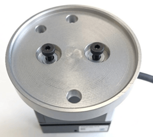
Note: After tightening, ensure that the adapter plate sits flush on the gripper housing. Clean the mating surface if necessary. Also, make sure that the screw heads do not protrude from the recess.
Remember to use the correct screws (low head cylinder screw DIN 7984, M4x12) for this step!
Mounting Gripper Jaws on Gripper Fingers
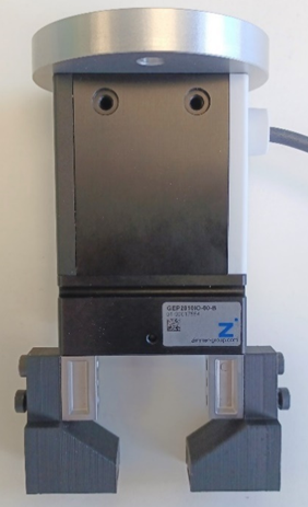
Next, in the following step, the gripper jaws are mounted on the base device if not already present. Please note that the gripper jaws are not included in the delivery package as they are always custom-made for specific applications. To mount them, press each jaw onto the screwing possibility of the gripper finger from the outside and fasten them using the four M4x12 screws.
Mounting Gripper on Robot Flange (Arm 3)
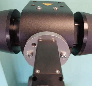
Next, the pre-assembled gripper is aligned and secured on the robot flange. To do this, start by inserting the centering pin (6x14 M6) into the hole in the robot flange.
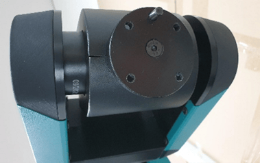
Afterwards, align the pre-assembled gripper using the centering pin and press it onto the robot flange in the correct orientation. It is important to ensure that the surfaces are clean and free of any contaminants. Once this is confirmed, secure the gripper to the robot using the cylinder screws DIN 6912, M6x12.
Electrical Final Assembly
In the final assembly step, the electrical final assembly is conducted to ensure data transmission between the robot and gripper. Simply connect the transmission cable to the right socket of Arm 3 on the robot. Once communication is established, the gripper can be controlled in horstOS via TOOL-OUTPUT-1 and TOOL-OUTPUT-2.