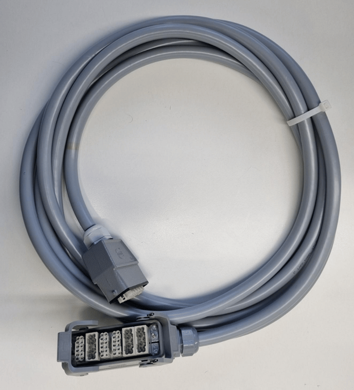
Interface cable to the machine tool (Machine Tending)
EMCO Standard Handling Interface 828D
General Information:
Note
This document serves as a helpful guide for installing the Component Kits. It does not provide a step-by-step installation manual in the traditional sense.
Safety notice
Seek professional assistance if needed to avoid dangerous situations and injuries.
Power supply
Before starting the assembly steps, ensure that the product is powered off. Once all assembly steps are completed, the power supply can be turned back on.
Assembly Parts
| Nr | Quantity | Designation |
|---|---|---|
| 1 | 1 | Interface Cable for Machine Tending with EMCO Standard Interface 828D |
Procedure
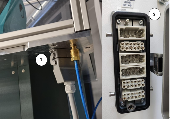
Before plugging in the interface, make sure that both the control and the machine tool are powered off. Then, connect the interface cable to the Solution Kit (1) and the machine tool (2).
Interface Description
The standard input/output assignment of the interface is described in the following table:
EMCO | HORST (Machine Tending) | ||||
Modul | Pin | Description: | Cable number. | Terminal | Input/Output (I/O) |
A | 1-2 | Emergency stop signal from EMCO to the handling system Channel 1. | 33 - 21 | X4.1 - X5.3 | TA - SI5A |
3-4 | Emergency stop signal from EMCO to the handling system Channel 2. | 35 - 22 | X4.5 - X5.4 | TB - SI5B | |
5-6 | Machine door closed on handling-system channel 1 | 34 - 23 | X4.2 - X5.5 | TA - SI6A | |
7-8 | Machine door closed on handling system channel 2 | 36 - 24 | X4.6 - X5.6 | TB - SI6B | |
11-12 | +24 volts from the handling system to EMCO. | 37 - 38 | X13.1 - X15.1 | 24V - GND | |
B | 1-2 | Emergency stop signal from the handling system to EMCO Channel 1. | 29 - 30 | X8.1 - X8.2 | SR5A1 - SR5A2 |
3-4 | Emergency stop signal from the handling system to EMCO Channel 2. | 31 - 32 | X8.3 - X8.4 | SR5B1 - SR5B2 | |
12 | +24 volts from EMCO to the Handling System. | 39 | X17.1 | External Voltage | |
C | 1 | Machine Ready for Operation | 1 | X1.6 | DI06 |
2 | Main spindle clamping device released | 2 | X1.7 | DI07 | |
3 | Main spindle clamping device released | 3 | X1.8 | DI08 | |
4 | Counter spindle clamping device released / Rear tailstock | 4 | X2.1 | DI09 | |
5 | Counter spindle clamping device clamped / Rear tailstock | 5 | X2.2 | DI10 | |
6 | Machine door opened and axes moved freely | 6 | X2.3 | DI11 | |
7 | Channel in Reset State | 7 | X2.4 | DI12 | |
8 | Program running | 8 | X2.5 | DI13 | |
9 | M0/M01 is displayed. | 9 | X2.6 | DI14 | |
10 | Release safety fence opening | 10 | X2.7 | DI15 | |
E | 1 | Release main spindle clamping device | 11 | X9.1 | DO01 |
2 | Clamp main spindle tool. | 12 | X9.2 | DO02 | |
3 | Release counter spindle clamping device / Move tailstock back | 13 | X9.3 | DO03 | |
4 | Clamp counter spindle tool / Move tailstock forward | 14 | X9.4 | DO04 | |
5 | Clean clamping devices | 15 | X9.5 | DO05 | |
6 | Close machine door / Start NC | 16 | X9.6 | DO06 | |
7 | Start the NC program. | 17 | X9.7 | DO07 | |
8 | Resetting the system allows you to clear any errors and start fresh with the machine operation. | 18 | X9.8 | DO08 | |
9 | Single piece operation | 19 | X10.1 | DO09 | |
10 | Open machine door | 20 | X10.2 | DO010 | |
Additional information regarding the interface can be found in the attached EMCO manual "EMCO Standard Handling Interface 828D".
Configuration in horstOS:
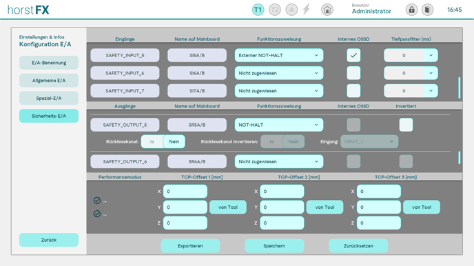
The safety inputs and outputs must be configured as follows:
SI5A/B -> External emergency stop -> Internal OSSD
SR5A/B -> Emergency stop