
Assembly aid signal light
General information
Note
This document is intended solely as support for assembling the component kit. It does not replace the applicable assembly instructions.
Safety notice
Get professional assistance if necessary to avoid dangerous situations and injuries
Assembly parts
| No. | Quantity | Designation |
|---|---|---|
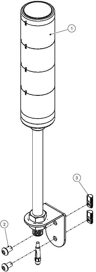
| 1 | 1 | Signal light with signal cable and mounting bracket |
| 2 | 2 | Pan head screw ISO 7380 M8x14 |
| 3 | 2 | T-slot nut 8I M8 |
Required tools
- Hexagon key 5 mm
Assembly steps
The signal light is screwed into the profile groove of the robot fence using the lens head screws ISO 7380 M8x14 and the T-slot nut 8I M8.
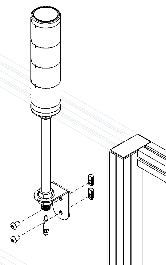
The signal cable is plugged into the labeled M8 connection socket on the top of the safety control cabinet and secured.
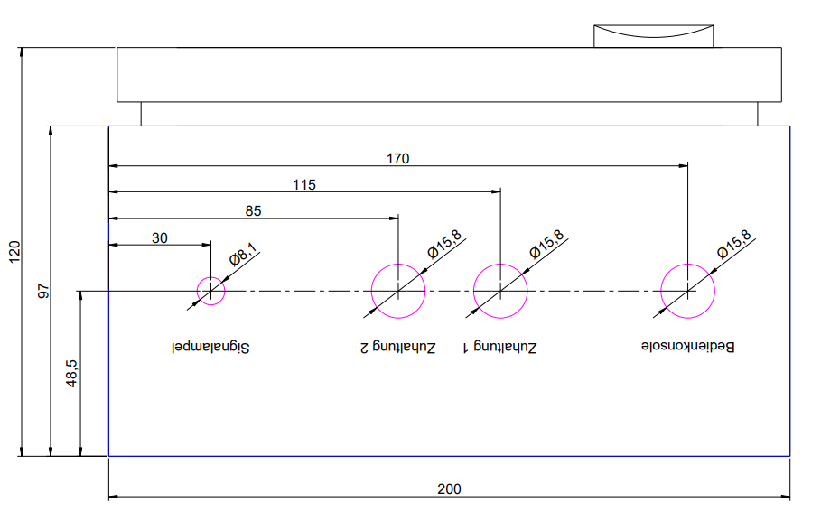
The cable can be guided in the profile groove and covered with the cover strip included in the scope of delivery of the robot fence.
Mounting position
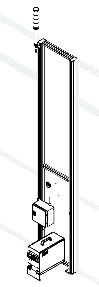
The signal light can be screwed to the internal profile grooves throughout the entire protective fence.
Interface
The signal light is controlled by the robot via 3 digital outputs. These can indicate the robot or program status through the configuration (function assignment) in horstOS. The following table shows the standard signal assignment of the traffic light in the Robotic Solution Machine Tending II:
| Digital output | Description | **Function assignment **in horstOS |
|---|---|---|
| SO1A | Signal light green | Two digital outputs + program running |
| SO2A | Traffic light yellow | Two digital outputs + program paused |
| SO2B | Signal light red | Two digital outputs + error |