
Component Kit Schunk double gripper MTB DG-JGP-P 64-1
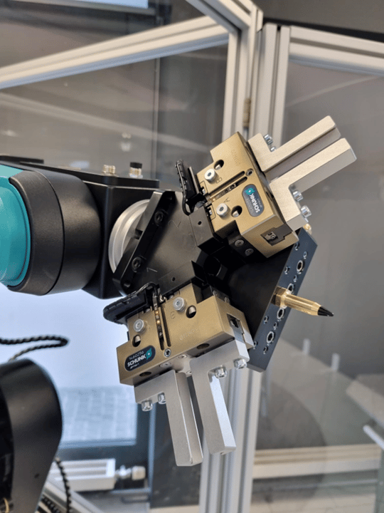
General Information:
Note
This document serves as a helpful guide for assembling the Component Kits. It is not a typical installation manual.
Safety notice
Before starting the assembly process, make sure to power off the robotic system. Seek professional assistance if needed to avoid any dangerous situations and potential injuries.
Assembly Parts
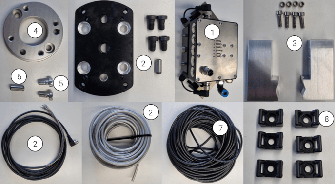
| Nr. | Quantity | Description |
|---|---|---|
| 1 | 1 | SCHUNK Application Kit MTB DG-JGP-P 64-1 consisting of: - Double gripper MTB DG-JGP-P 64-1 - Air blow nozzle |
| 2 | 1 | SCHUNK Robot Connection Package MTB CNK-SG/DG-RF1 consisting of: - Gripper adapter plate with 4x M6x10 screws. - Signal cable - Air hose with a diameter of 6mm |
| 3 | 2 | SCHUNK Finger Blanks MTB AUB-JGP-P 64/15 consisting of: - Two finger blanks - Four sleeves - Four screws M4x16 |
| 4 | 1 | ISO9409-Flange |
| 5 | 2 | Cylinder screw DIN 7984, M6x16 |
| 6 | 1 | Cylinder pin DIN 7, M6 |
| 7 | 1 | Spiral hose |
| 8 | 6 | Cable tie holder and 6 mm cable tie |
Required Tools:
Allen key sizes of 2.5 mm, 5 mm, and 8 mm
Open-end wrench 10 mm
Procedure:
Step 1: Mounting the Adapter Plate on the Robot Flange (Only for Robot Horst 600, 900, 1000, 1400)
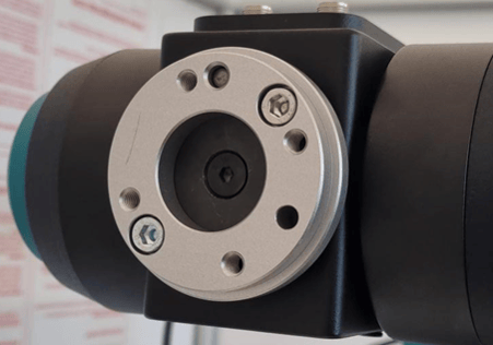
In the first step, mount the ISO 9404 flange onto the robot flange.
Start by inserting the centering pin DIN 7 M6 into the corresponding hole in the robot flange. Then, align the ISO 9404 flange in the correct orientation over the centering pin on the robot flange. Make sure that both surfaces on the flange and the adapter piece are free of any dirt or debris. Use the cylinder screws DIN 7984 M6x16 for securing the flange in place.
Step 2: Mounting the adapter plate from the MTB CNK-SG/DG-RF1 connection package
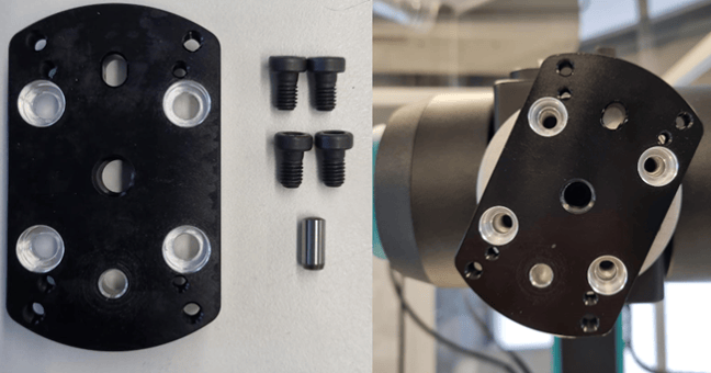
Next, proceed to mount the gripper adapter plate from the connection package onto the ISO 9409 flange. To ensure proper orientation, align the robot flange so that the pin hole faces upward. Then, secure the gripper adapter plate in place using the provided M6 screws.
Pre-assembly of Finger Blanks and Air Blow Nozzle
Next, proceed to attach the included air blow nozzle to the double gripper MTB DG-JGP-P 64-1. Unscrew the plug, and use a 10 mm wrench to mount the air blow nozzle securely. |
| |
Next, proceed to mount the finger blanks onto the gripper jaws. Align the finger blanks over the included sleeves in the gripper jaws and secure them in place using the provided M4x16 screws. |
| |
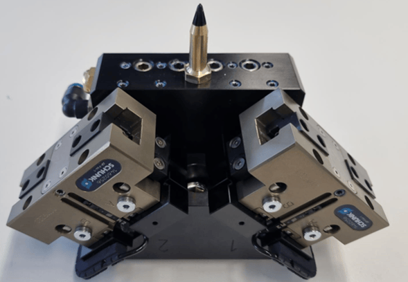
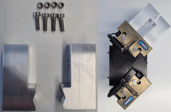
Mounting the double gripper on the robot.
Next, mount the pre-assembled double gripper on the robot flange. Align the gripper over the two pressed-in alignment pins on the gripper adapter plate, then secure it in place using the integrated connecting screw on the gripper (Tool: 8 mm hex key).
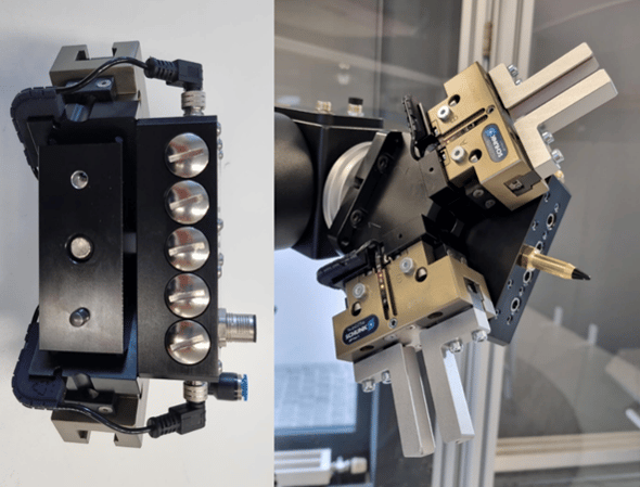
Next, proceed to screw in the signal cable and insert the air hose.
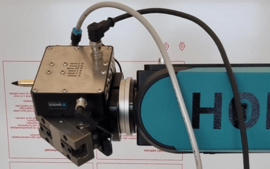
Attaching the external energy chain
The external energy chain is guided along the robot arm using the cable tie holders. These holders are mounted on the robot with the housing screws. Refer to the illustration for the correct position and orientation.
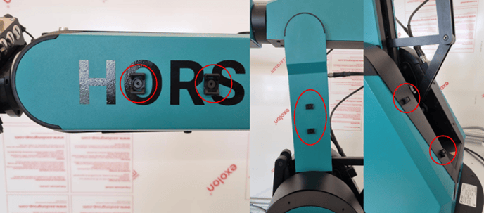
Next, wrap the signal and air hose on a length of 2m with spiral hose for protection and organization.
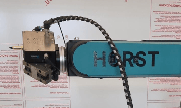
Finally, secure the energy chain to the cable tie holders using cable ties. Make sure to leave enough space between the loops of the energy chain at each fixing point so that the individual axes can still have the necessary range of motion for the application.
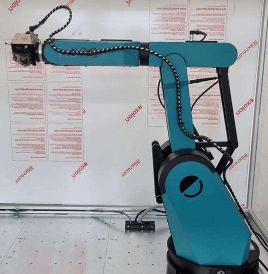
Connection to CONTROL
The signal cable can be connected to the robot controller as follows:
| Control Terminal | Cable Color Signal Line | Function |
|---|---|---|
| X11.3 24V | brown | 24 VDC0 |
| X14.1 GND | blue | GND |
| X1.1 DI01 | whit | Sensor Gripper 1, Location A |
| X1.2 DI02 | green | Sensor Gripper 1, Position B |
| X1.3 DI03 | pink | Sensor Gripper 2, Location A |
| X1.4 DI04 | yellow | Sensor Gripper 2, Location B |
| X9.1 DO01 | black | Teaching Function, Gripper Sensor 1 |
| X9.2 DO02 | gray | Teaching Function, Gripper Sensor 2 |
| X9.3 DO03 | red | Switch Gripper 1 |
| X9.4 DP05 | purple | Switch Gripper 2 |
| X9.5 DO06 | gray pink | Release Signal |
| X9.6 DO07 | red blue | Switch Air Blow Nozzle |