SensoPart Visor Robotic
This article describes communication between the SensoPart Visor Robotic camera system and the HORST robot system.
1. Version information
The article, example programs and functions refer to:
- Robot control software version 2023.11.01
- SensoPart Visor V2.10
2. Introduction
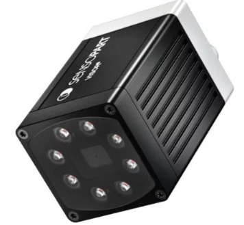
Visor Robotic is a smart 2D camera system for object localisation. It provides different detectors for locating and inspecting objects, including contour, pattern-matching and BLOB detectors. It can also check brightness, contrast and greyscale values, and measure components.
This guide focuses on communication between HORST and the Visor.
3. System setup
Refer to SensoPart's documentation for mechanical assembly and electrical wiring. To supply power to the Visor, connect the blue signal-cable wire to gnd and the brown wire to 24 V. If the digital interface is not used, no further wires are required for the arrangement described here.
Download and install the appropriate Visor PC software from SensoPart to set up and configure the sensor.
Connect the Visor to a PC using a network cable. Both devices must be in the same IP address range. The factory address of the Visor is 192.168.100.100. In this setup, the first three blocks of the PC's static address must match and the final block must differ; 192.168.100.25 is an example. Refer to the Visor user manual for further details.
Start the installed software. Enter the sensor address in the IP address field to add the sensor. In this article's example, the Visor was subsequently assigned 192.168.2.210.
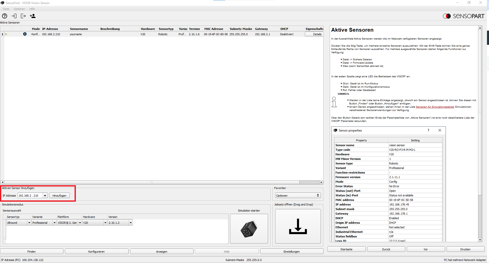
Once the sensor is found, it can be configured. This guide covers the settings needed for communication. The Visor user manual describes sensor configuration and object teaching.
4. TCP/IP communication
The following sections describe TCP/IP communication. The Visor user manual covers the digital interface, which can be sufficient when the application needs only simple information such as a pass/fail result.
SensoPart's Visor communication manual provides the TCP/IP protocol details.
4.1. Set the IP address
The robot must be in the same IP address range as the Visor. See Change the robot's IP address for the robot settings.
4.2. Establish a connection
The following function establishes a connection from horstOS to the camera system:
// Camera data
var IPCamera = "192.168.2.210";    // IP Camera
var PortCameraWrite = 2006;        // Port Camera to write data to camera
var PortCameraRead = 2005;         // Port Camera to read data from camera

var SocketWrite = null;
var SocketRead = null;

// Establish connection to camera
connectToCamera();

// Establish connection to camera
function connectToCamera()
{
    // Socket write
    var ConnectSuccessWrite = null;
    [ConnectSuccessWrite, SocketWrite] = openSocket(IPCamera, PortCameraWrite, 5000);
    if (ConnectSuccessWrite != 1)
    {
        showError("The robot was not able to connect to the Camera-Write Port!");
        exitRobotScript();
    }

    // Socket read
    var ConnectSuccessRead = null;
    [ConnectSuccessRead, SocketRead] = openSocket(IPCamera, PortCameraRead, 5000);
    if (ConnectSuccessRead != 1)
    {
        showError("The robot was not able to connect to the Camera-Read Port!");
        exitRobotScript();
    }

    showHint("Connected to camera");
}
The example uses port 2005 to read information from the camera and port 2006 to send commands to it.
4.3. Send a trigger command
After a connection has been established, use the following function to trigger the camera:
// Trigger camera
triggerCamera();


// Trigger camera
function triggerCamera()
{
    var WriteSuccess = writeSocket(SocketWrite, "TRG");
    if (WriteSuccess != 1)
    {
        showError("An error occured while triggering the camera!");
        closeCameraConnection();
        exitRobotScript();
    }

    showHint("Triggering camera");

    // Check answer from camera
    var [ReadSuccess, Data] = readSocket(SocketWrite, 256, 2000);
    if (Data.localeCompare("TRGP") != 0)
    {
        showError("The camera was not able to execute the trigger command!");
        closeCameraConnection();
        exitRobotScript();
    }
}
The camera must be in Run mode and Trigger must be selected as the trigger mode. Otherwise, horstOS may display: “The camera was not able to execute the trigger command!”
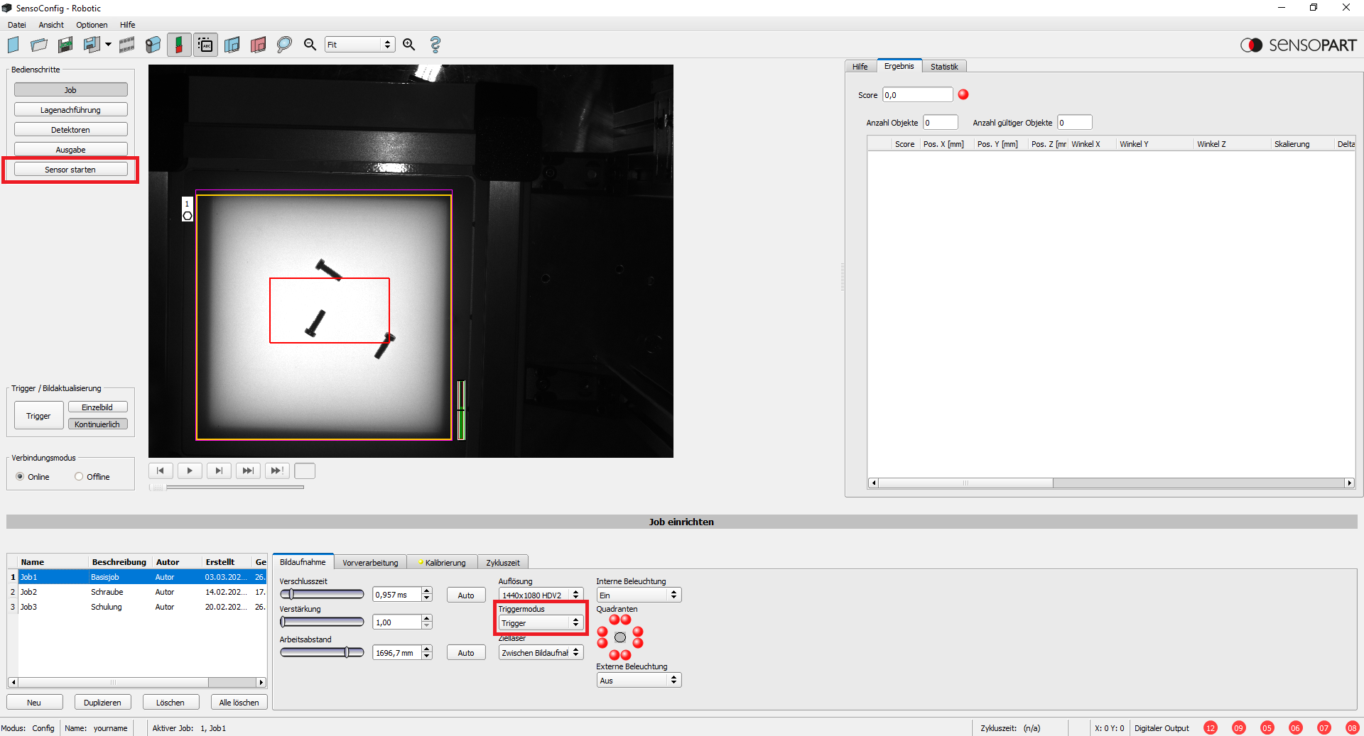
4.4. Change the camera job
Use the following function to change the camera job from horstFX:
// Change camera job
CamJob = "002";
changeJob();

// Change camera job
function changeJob()
{
    var WriteSuccess = writeSocket(SocketWrite, "CJB"+CamJob);
    if (WriteSuccess != 1)
    {
        showError("An error occured while changing the camera job!");
        closeCameraConnection();
        exitRobotScript();
    }

    // Check answer from camera
    var [ReadSuccess, Data] = readSocket(SocketWrite, 256, 2000);
    if (Data.localeCompare("CJBPT"+CamJob) != 0)
    {
        showError("The camera was not able to execute the change camera job command!");
        closeCameraConnection();
        exitRobotScript();
    }

    showHint("Changing camera job to job: " + CamJob);
}
The sensor must again be in Run mode. The job identifier must contain exactly 3 characters: to select job 2, assign the string "002" to CamJob.
4.5. Read object information
Read the camera's object information with the following function:
// Grasp data
var GraspHeight = 0.1305;       // Height of pick point
var MoveFactor = 0.05;          // Distance approach point to pick point
var UseStaticRZCoord = 0;       // If 1 - Static angle RZ is used. E.g. grasp round objects
var StaticRXCoord = 180;        // Grasp angle RX
var StaticRYCoord = 0;          // Grasp angle RY
var StaticRZCoord = 90;         // Static angle RZ. If RZ coord from camera should be ignored

// Get object positions
var CamData = getObjectPositions();

// Get object positions
function getObjectPositions()
{
    var [ReadSuccess, Data] = readSocketToDelimiter(SocketRead, "#", 5000);
    if (ReadSuccess != 1)
    {
        showError("An error occured while reading data from the camera!");
        closeCameraConnection();
        exitRobotScript();
    }

    // showInfo(Data);

    // Split camera data
    var Splitted = Data.split(",");
    var AmountObjects = Splitted[0];            // Amount of all objects
    var AmountPickableObjects = Splitted[1];    // Amount of pickable objects
    var CamX = Splitted[2];                     // Object coordinate X
    var CamY = Splitted[3];                     // Object coordinate Y
    var CamZ = Splitted[4];                     // Object coordinate Z
    var CamRX = Splitted[5];                    // Object coordinate RX
    var CamRY = Splitted[6];                    // Object coordinate RY
    var CamRZ = Splitted[7];                    // Object coordinate RZ

    // Typecast, convert to meter an degree
    AmountObjects = parseFloat(AmountObjects);
    AmountPickableObjects = parseFloat(AmountPickableObjects);
    CamX = parseFloat(CamX)/1000/1000;
    CamY = parseFloat(CamY)/1000/1000;
    CamRZ = parseFloat(CamRZ)/1000;

    // If 1 - Static angle RZ is used. E.g. grasp round objects
    if (UseStaticRZCoord == 1)
    {
        CamRZ = StaticRZCoord;
    }

    // Normal vector for grasp with angle
    var NormalVector = getSurfaceNormalByEuler(StaticRXCoord, StaticRYCoord, CamRZ);
    // Get approach and departure positions
    var ApproachCamX = CamX - (MoveFactor*NormalVector.getX());
    var ApproachCamY = CamY - (MoveFactor*NormalVector.getY());
    var ApproachCamZ = GraspHeight - (MoveFactor*NormalVector.getZ());

    return{AmountObjects: AmountObjects,
            AmountPickableObjects: AmountPickableObjects,
            CamX: CamX, CamY: CamY, CamRZ: CamRZ,
            ApproachCamX: ApproachCamX, ApproachCamY: ApproachCamY, ApproachCamZ: ApproachCamZ};
}
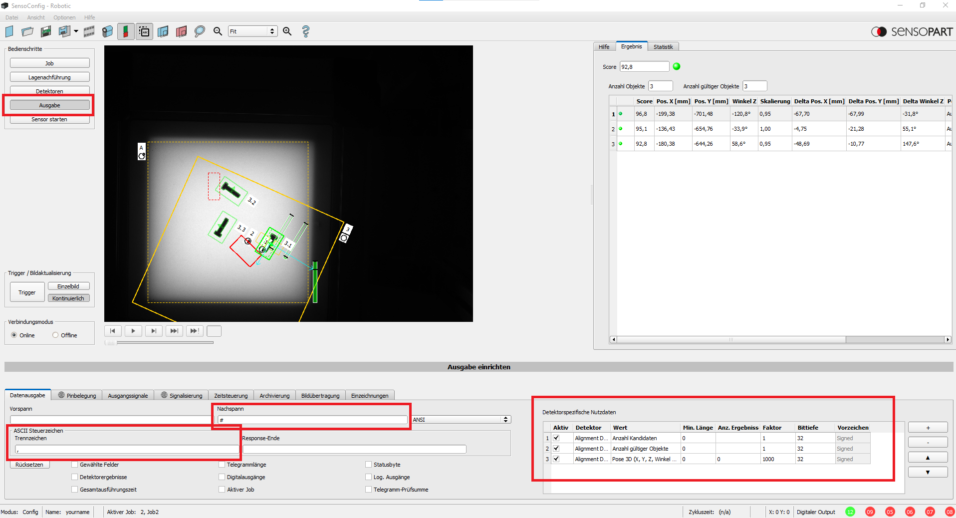
For the parser to read the object parameters correctly, configure the following settings in the Visor's Output area:
- Set the trailer to
#. horstOS reads until this character occurs in the message, allowing it to receive the complete message. - Set the separator to
,so that the individual values are comma-separated. - Add the detector results in this order: 1. Number of candidates, 2. Number of valid objects, 3. Pose 3D.
4.6. Approach the object
The following waypoints use the object position determined by the camera:
// Grasp data
var GraspHeight = 0.1305;       // Height of pick point
var MoveFactor = 0.05;          // Distance approach point to pick point
var UseStaticRZCoord = 0;       // If 1 - Static angle RZ is used. E.g. grasp round objects
var StaticRXCoord = 180;        // Grasp angle RX
var StaticRYCoord = 0;          // Grasp angle RY
var StaticRZCoord = 90;         // Static angle RZ. If RZ coord from camera should be ignored

// Get object positions
var CamData = getObjectPositions();

// Approach point pick position
move({
    "name": "ApproachPick",
    "moveType": "JOINT",
    "poseRelation": "ABSOLUTE",
    "anyConfiguration": false,
    "tool": "No Tool",
    "coordSystem": "Basis",
    "speed.ratio": 1.0,
    "blendradius.orient": 180.0,
    "blendradius.xyz": 0.02,
    "target": {"xyz+euler": [CamData.ApproachCamX, CamData.ApproachCamY, CamData.ApproachCamZ, StaticRXCoord, StaticRYCoord, CamData.CamRZ]}
});

// Pick point
move({
    "name": "Pick",
    "moveType": "LINEAR",
    "poseRelation": "ABSOLUTE",
    "anyConfiguration": false,
    "tool": "No Tool",
    "coordSystem": "Basis",
    "speed.ratio": 0.7,
    "target": {"xyz+euler": [CamData.CamX, CamData.CamY, GraspHeight, StaticRXCoord, StaticRYCoord, CamData.CamRZ]}
});

// Departure point pick position
move({
    "name": "DeparturePick",
    "moveType": "LINEAR",
    "poseRelation": "ABSOLUTE",
    "anyConfiguration": false,
    "tool": "No Tool",
    "coordSystem": "Basis",
    "speed.ratio": 1.0,
    "blendradius.orient": 180.0,
    "blendradius.xyz": 0.02,
    "target": {"xyz+euler": [CamData.ApproachCamX, CamData.ApproachCamY, CamData.ApproachCamZ, StaticRXCoord, StaticRYCoord, CamData.CamRZ]}
});
The robot approaches and leaves the object through an intermediate point. MoveFactor specifies the distance between that point and the pick position. A value of 0.05 corresponds to 5 cm.
GraspHeight defines the height of the object position. Teach this by manually approaching the surface to be gripped and assigning its Z position to the variable.
UseStaticRZCoord selects a fixed StaticRZCoord orientation for gripping. This can be useful for round objects.
Use StaticRXCoord and StaticRYCoord to set an approach angle around RX or RY. This can help with objects that lie at an angle on a surface, such as screws with a large head.
5. Textual example program
The downloadable example contains all functions and waypoints described in section 4, Communication. When a pickable object is available, the robot approaches it and moves it to a deposit position, then triggers another image. If no object with a valid grasp is detected, a new trigger is sent every second.
SensoPart Vision textual example program — ZIP
6. Graphical example program
The graphical example contains the same functions and waypoints from section 4, Communication and provides the same behaviour as the textual example in section 5. Use it as a starting point and adapt it to the application.
SensoPart Vision graphical example program — ZIP
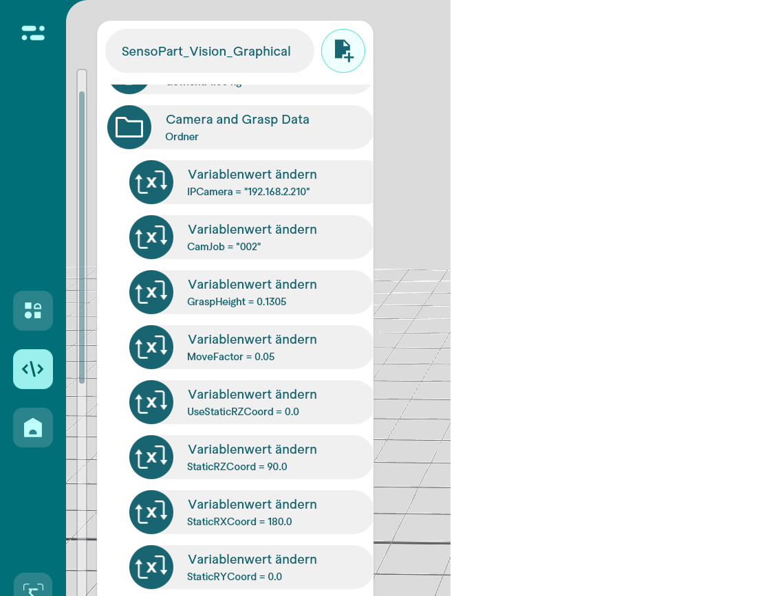
Set the required variables described in section 4, Communication at the beginning of the program:
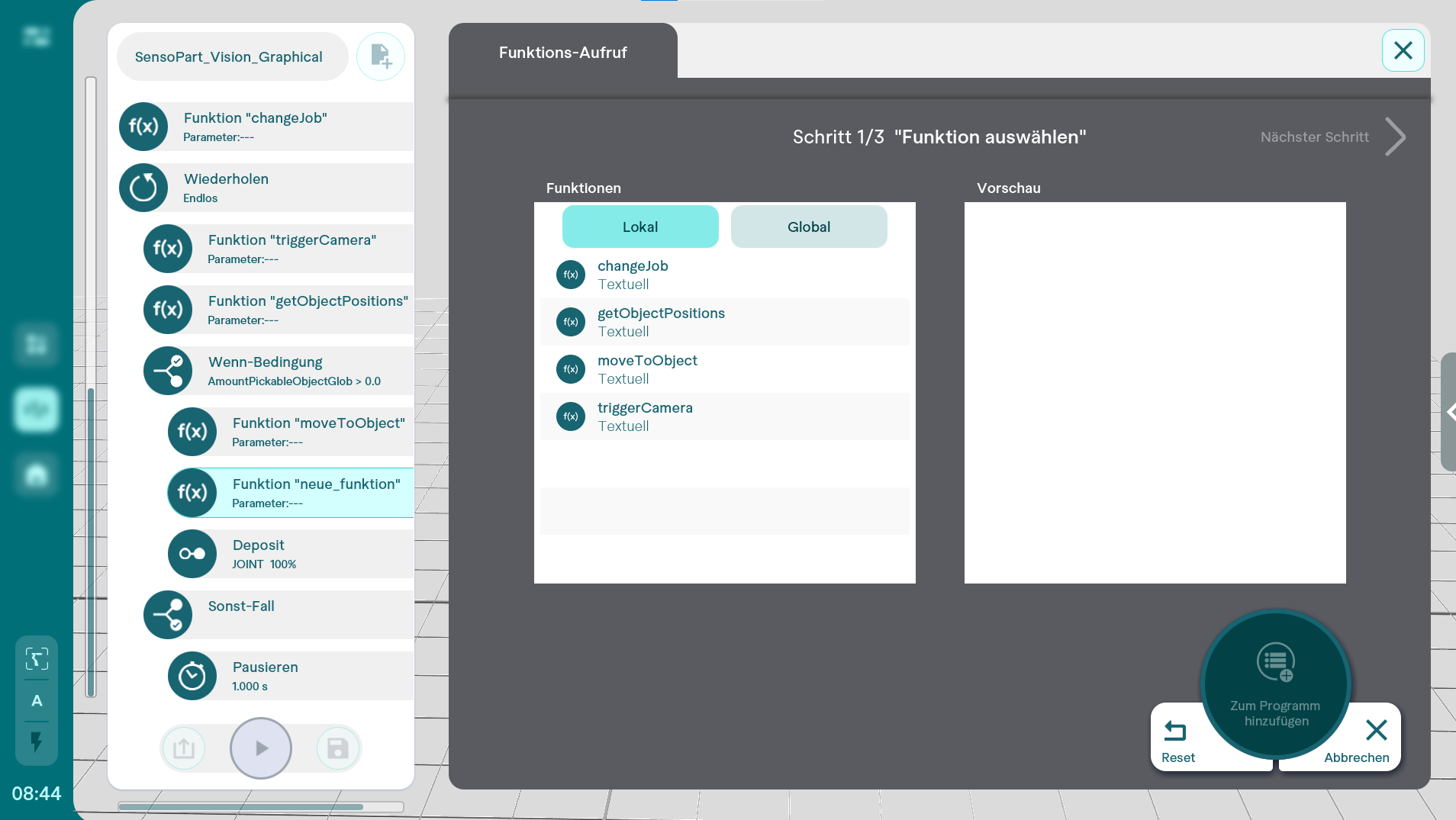
Add the following functions to the program for communication with the robot: