
Assembly aid Harting connector
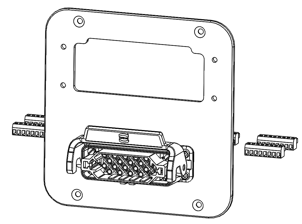
General Guidelines
Note
This document serves as a helpful guide for assembling the Component Kits. It does not constitute a traditional assembly manual.
Safety notice
Seek professional assistance if necessary to avoid dangerous situations and injuries.
Assembly parts
| Nr. | Quantity | Description |
|---|---|---|
| 1 | 1 | Switch cabinet rear panel with Harting connector |
| 2 | 1 | 40-pin male Harting connector,• Enclosure: Han 40DD M-c • Insert: Han16A-agg-LB |
| 3 | 1 | Signal cable with detachable connection blocks for CONTROL |
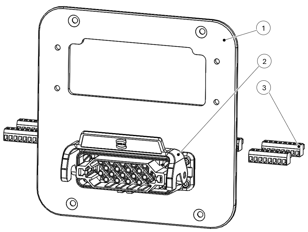
Required Tools:
- Hex key 2.5mm
Assembly steps
Remove the cable gland from the rear panel and detach the rear panel from the CONTROL unit.
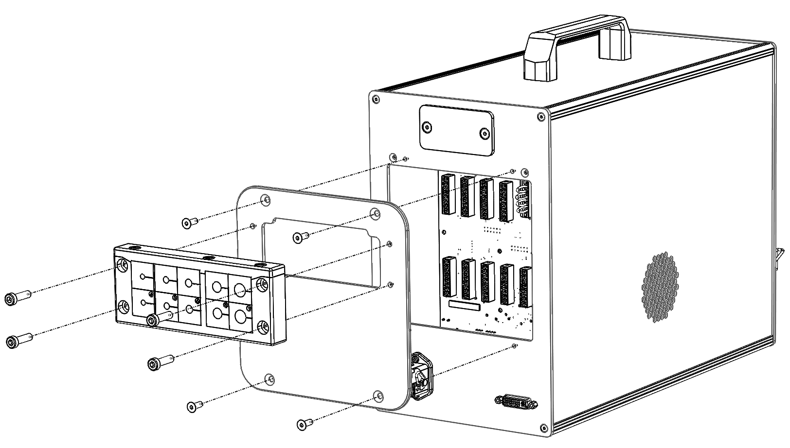
Insert the connection blocks according to the labeling.
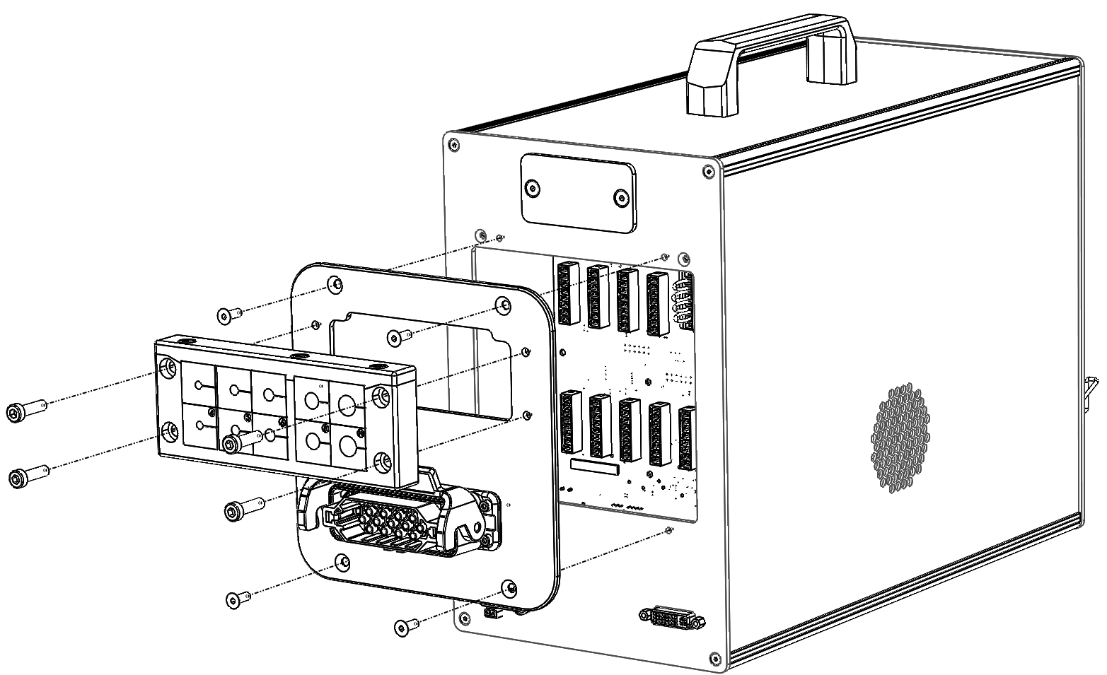
Mount the rear panel with the Harting connector.
Interface
The standard pin configuration on the Harting connector is as follows:
| Pin/Cable number | Terminal | E/A |
1 | X1 | DI01 |
| 2 | DI02 | |
| 3 | X2 | DI09 |
| 4 | DI10 | |
| 5 | DI11 | |
| 6 | DI12 | |
| 7 | DI13 | |
| 8 | DI14 | |
| 9 | DI15 | |
| 10 | DI16 | |
| 11 | X9 | DO01 |
| 12 | DO02 | |
| 13 | DO03 | |
| 14 | DO04 | |
| 15 | DO05 | |
| 16 | DO06 | |
| 17 | DO07 | |
| 18 | DO08 | |
| 19 | X10 | DO09 |
| 20 | DO10 | |
| 21 | X5 | SI6A |
| 22 | SI6B | |
| 23 | SI7A | |
| 24 | SI7B | |
| 25 | X7 | SO4A |
| 26 | SO4B | |
| 27 | X13 | +24V |
| 28 | X15 | GND |
| 29 | X8 | SR5A1 |
| 30 | SR5A2 | |
| 31 | SR5B1 | |
| 32 | SR5B2 | |
| 33 | X4 | TA |
| 34 | TA | |
| 35 | TB | |
| 36 | TB | |
| 37 | Reserve | - |
| 38 | - | |
| 39 | - | |
| 40 | - |
The cable diagram of the signal cable Harting connector can be found at the following link: