
Robot base accessories: Positioning unit (assembly aid)
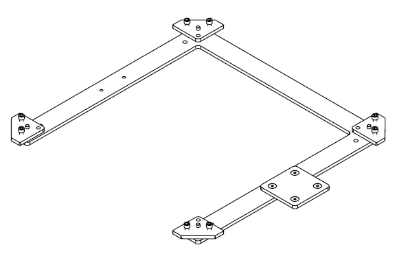
General information
Note
This document is intended solely as an aid to the assembly of the Component Kit. It does not replace the applicable assembly instructions.
Safety notice
Get professional assistance if necessary to avoid dangerous situations and injuries
Ensure pre-orientation
When lowering the RB (or the tray holder with legs) into the positioning unit, sufficient pre-orientation must be ensured: The positioning cones must not rest on the edges of the bushings to ensure that the cones slide smoothly into the bushings. Otherwise it can damage the positioning cones.
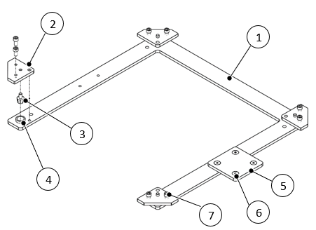
Assembly parts
| Number | Quantity | Designation |
|---|---|---|
| 1 | 1 | Base plate |
| 2 | 4 | Cone plate |
| 3 | 4 | Position cone |
| 4 | 1 | Rifle |
| 5 | 1 | Connecting plate |
| 6 | 4 | M10x20 |
| 7 | 8 | M10x20 |
Required tools
- Hexagon key 6 mm
- Hexagon key 8 mm
Assembly steps
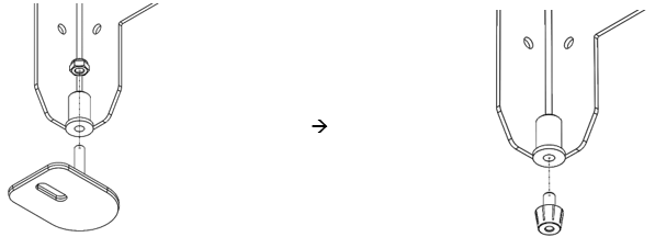
- To use the positioning unit, the adjustable feet are replaced by positioning cones. With the tray holder with legs, the positioning cones can be inserted directly:
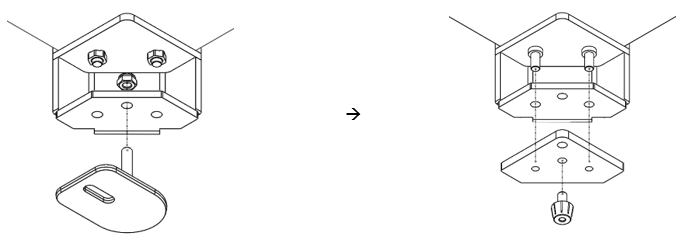
With the RB, the positioning cones are inserted into the cone plate. The cone plate is then screwed to the RB with the enclosed DIN 912 M10x20 screws:
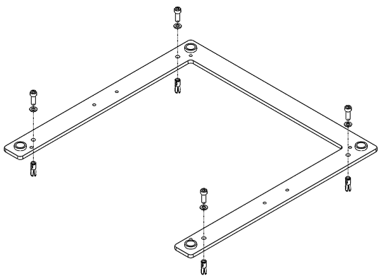
- The base plate is anchored in the desired position in the floor using the screws, washers and dowels supplied with the RB (or the tray holder with legs):
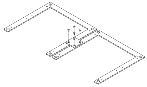
To facilitate the positioning of several positioning units relative to each other, they can be connected to each other using the connecting plate with the DIN7991 M10x20 screws:
For positioning, the RB (or tray holder with legs) is lowered into the positioning unit using an industrial truck . The positioning cones center the RB (or tray holder with legs) in the sockets of the positioning unit. To guarantee tipping stability, the RB can be fixed
to the positioning unit using M10x25 screws via the cone plate.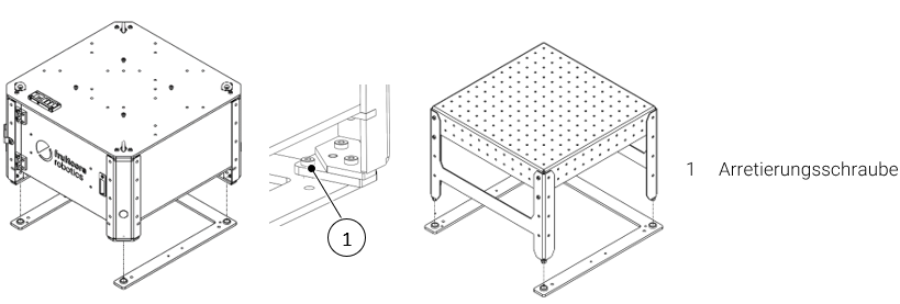
When centering the RB for the first time, the anchor plate should be loosened (screws DIN 912 M10x20) to allow initial alignment of the positioning cones to the bushings. After positioning the RB in the positioning unit, the anchor plate must be fixed again. Accordingly, the fixing screws of the legs are loosened for the tray holder with legs.