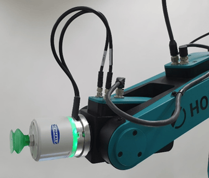
Component Kit Schmalz ECBPMi
General Information:
Note
This document serves as a guide to assist with the assembly of the Component Kits. Please note that it does not constitute a traditional assembly manual.
Safety notice
Seek professional assistance if necessary to avoid dangerous situations and injuries.
Power supply
Turn off the power to the robotic system before proceeding with the following steps. Once all steps have been completed, you can safely turn the electrical power back on.
Assembly Parts
Quantity | Description | Illustration |
1 | Schunk Cobot Pump Mini ECBPMi |
|
1 | Adapter plate for ISO 9409 flange TK504 | |
4 | Cylinder screw DIN 7984, M6x10 (not shown) | |
1 | Cylinder pin DIN 7, M6 (not shown) |
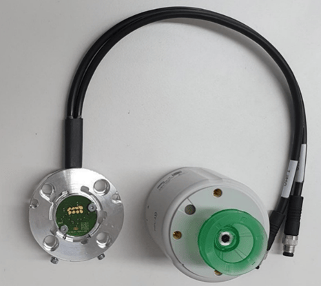
Required tools:
- 5mm Allen key
Procedure
Step 1: Mounting the adapter plate on the robot flange
In the first step, mount the adapter plate onto the robot flange. Start by inserting the centering pin DIN 7 M6 into the corresponding hole on the robot flange.
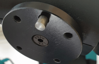
Next, press the adapter plate onto the robot flange in the correct orientation using the centering pin. Ensure that both the flange and adapter plate surfaces are clean from any dirt or debris.
The plate must be visible in its mounted state for proper orientation. Additionally, the electrical base element can be fastened in two different orientations. While the orientation is flexible, it should be chosen based on cable management and application requirements. Use cylinder screws DIN 912, M6x10 for securing the position.
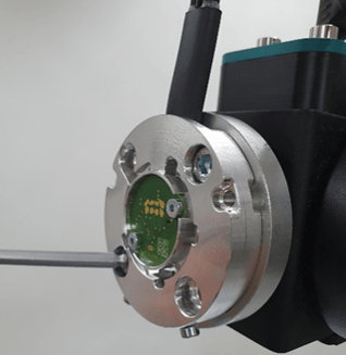
Step 2: Mounting the base unit on the electrical interface
Next, mount the base unit onto the electrical interface so that the end faces align, ensuring proper electrical contact. Position the base unit in a way that allows the bolts on the back to fit into the socket. By manually turning the base unit (approximately 90° clockwise), it will securely lock into place in the socket.
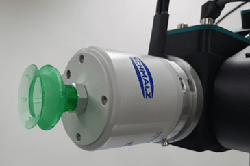
To secure the position and ensure a reliable connection between the gripper and the base, use a 2.5mm Allen key to tighten the cylinder screws located on the side.
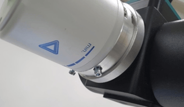
Step 3: Electrical Final Assembly
In the final assembly step, the electrical final assembly is carried out to ensure data transmission between the robot and gripper. Here, the connecting cable is attached to Arm 3's electrical interface. The cables are labeled as User 1 and User 2. Connect the cable labeled User 1 to the right socket of the robot interface and the cable labeled User 2 to the left socket of the robot. When connected correctly, the vacuum gripper will illuminate green, indicating it is ready for operation. The gripper can now be controlled directly through the horstOS robot control.